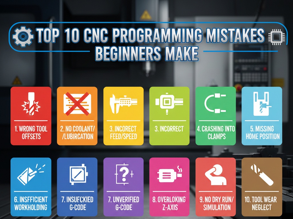
Milling a Simple Cube: Step-by-Step CNC Program
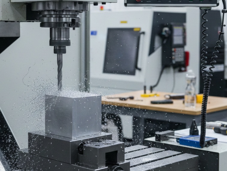
This guide provides a comprehensive breakdown of a CNC program (G-code) designed to mill a 2″ x 2″ x 2″ cube from a slightly oversized aluminum block (e.g., 2.25″ stock).
1. The Strategy: Planning the Cuts
Before writing a single line of code, we must define our setup. For this program, we will use a 3/4″ Carbide End Mill.
- Work Offset (G54): The “Zero” point is the top-left corner of the finished cube.
- Stock Size: 2.25″ x 2.25″ x 2.25″
- Final Size: 2.00″ x 2.00″ x 2.00″
- Safety Height: 1.0″ above the part.
2. The Program Header (Safety First)
Every professional G-code program starts with a safety block to ensure the machine is in a known state.
G-Code
%
O1001 (SIMPLE CUBE MILLING)
(T1: 0.75 END MILL)
G20 (Inches mode)
G17 (XY Plane selection)
G40 (Cutter compensation cancel)
G49 (Tool length offset cancel)
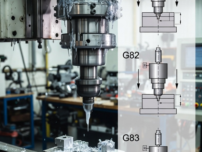
G80 (Canned cycle cancel)
G90 (Absolute positioning)
G94 (Feed per minute mode)
G20: Sets the machine to inches. If you are in Europe or using metric, use G21.
G90: Tells the machine that all coordinates are relative to the Zero point (G54), not the current tool position.
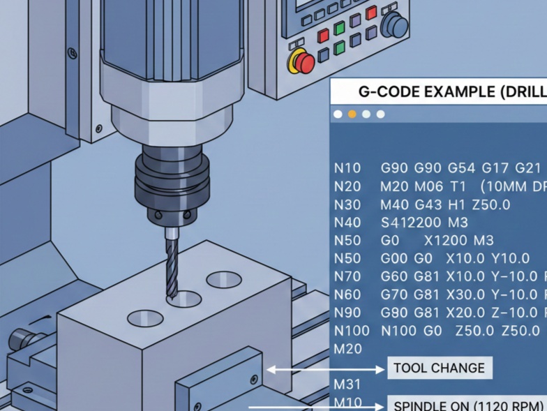
3. Tool Change and Spindle Start
Next, we call the tool and set the cutting speeds.
G-Code
N10 T1 M06 (Load Tool 1)
S3500 M03 (Spindle on Clockwise at 3500 RPM)
G54 G00 X-0.5 Y0.5 (Rapid to starting position)
G43 H01 Z1.0 M08 (Activate Tool Offset 1, move to safety height, Coolant ON)
S3500: Spindle speed. For Aluminum with a 0.75″ tool, this is a conservative starting point.
G43 H01: This is the most important line for safety. It tells the machine how long the tool is based on the offset stored in “H01.”
4. Operation 1: Facing the Top
We need to ensure the top surface is perfectly flat and at the correct $Z$ height. We will take two passes.
G-Code
(FACE TOP)
Z0.1 (Rapid to 0.1 above part)
G01 Z0.0 F20.0 (Feed down to finished top surface)
X2.5 F40.0 (Pass 1 across the top)
G00 Y-0.5 (Move over for next pass)
G01 X-0.5 (Pass 2 across the top)
G00 Z1.0 (Retract to safety height)
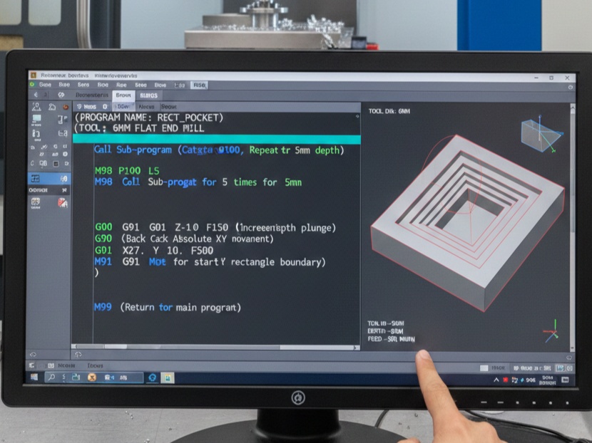
5. Operation 2: Roughing the Perimeter
We will use a Square Pocket/Contour strategy. Since our tool is 0.75″ diameter, we must account for the radius. We will cut in two depth steps ($Z$ levels) to avoid overloading the tool.
First Depth Pass ($Z = -1.0$)
G-Code
(ROUGH PERIMETER - PASS 1)
X-0.5 Y0.5 (Starting position)
Z-1.0 (Plunge to 1 inch deep)
G01 G41 D01 X0.0 Y0.0 F30.0 (Engage Cutter Comp - Move to corner)
Y-2.0 (Cut left side)
X2.0 (Cut bottom side)
Y0.0 (Cut right side)
X0.0 (Cut top side)
G40 G01 X-0.5 Y0.5 (Cancel Comp and move away)
Key Concept: G41 (Cutter Compensation)
$G41$ tells the CNC to offset the tool to the left of the programmed line by the radius of the tool (stored in “D01”). This allows you to program the actual dimensions of the cube (2.0×2.0) rather than doing the math for the tool center.
Second Depth Pass ($Z = -2.0$)
We repeat the path at the final depth.
G-Code
(ROUGH PERIMETER - PASS 2)
Z-2.0
G01 G41 D01 X0.0 Y0.0 F30.0
Y-2.0
X2.0
Y0.0
X0.0
G40 G01 X-0.5 Y0.5
6. Operation 3: Finishing Pass
To get a “mirror” finish, we take a very light cut (0.005″) at a higher feed rate.
G-Code
(FINISH PASS)
S4000 M03 (Speed up spindle)
G01 G41 D01 X0.0 Y0.0 F50.0
Y-2.0
X2.0
Y0.0
X0.0
G40 G01 X-0.5 Y0.5
7. Program End (The Exit Strategy)
Never stop the machine while the tool is near the part. You must retract and clear the work area.
G-Code
G00 Z1.0 M09 (Retract and Coolant OFF)
G53 G49 Z0 M05 (Move Z to home position, Spindle OFF)
G53 Y0 (Move table forward for easy part removal)
M30 (Program End and Reset)
%
8. Summary of G-Codes Used
| Code | Description |
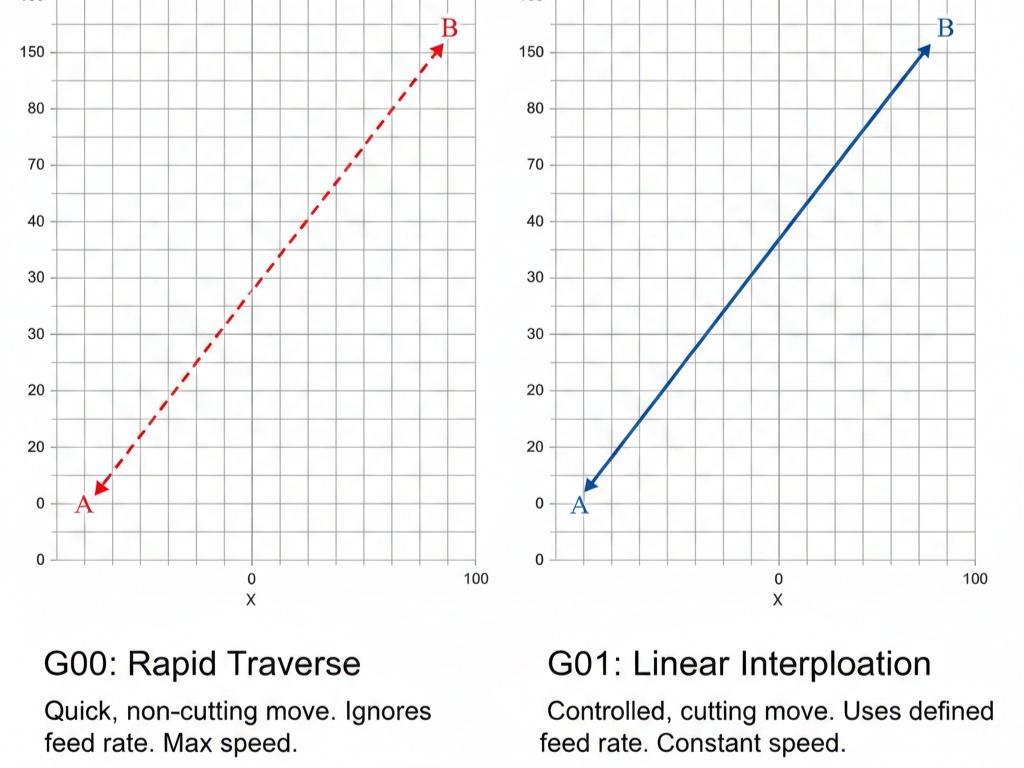
| G00 | Rapid motion (non-cutting) |
| G01 | Linear interpolation (cutting feed) |
| G41 | Cutter Compensation Left |
| G43 | Tool Length Compensation Positive |
| G54 | Work Coordinate System 1 |
| M03 | Spindle On (Clockwise) |
| M06 | Tool Change |
Simple G-Code Program (Fanuc/Haas Style)
This program assumes a 10mm End Mill (Tool 1) and that your stock is slightly larger than 50mm.
G-Code
(PROGRAM NAME: SIMPLE_CUBE)
(T1: 10MM END MILL)

G21 G90 G40 G80 G17 (Metric, Absolute, Cancel offsets, XY Plane)
T1 M06 (Tool Change to Tool 1)
S2500 M03 (Spindle 2500 RPM, Clockwise)
G54 G00 X-10 Y-10 (Move to start position outside stock)
G43 H01 Z10 (Tool length offset, Rapid to 10mm above)

(FACING PASS AT Z0)
G01 Z0 F500 (Feed down to top surface)
G01 X60 F800 (Face across the top)
G00 Z5 (Lift up)

(CONTOUR SIDES - 50x50 CUBE)
G00 X-10 Y-10 (Position for side cut)
G01 Z-10 F400 (Plunge to depth)
G01 G41 D01 X0 Y0 (Cutter compensation left, move to corner)
G01 Y50 (Mill side 1)
G01 X50 (Mill side 2)
G01 Y0 (Mill side 3)
G01 X0 (Mill side 4)
G01 G40 X-10 Y-10 (Cancel compensation, move away)

G00 Z50 M05 (Retract and stop spindle)
G28 G91 Z0 (Home Z axis)
M30 (End of program)
Critical Safety Tips
- Dry Run: Run the program without a part or tool to see if the movements look correct.
- Distance-to-Go: Use the “Distance-to-Go” screen on your controller to ensure the tool isn’t about to crash into the vise.
- Feed Hold: Keep your hand on the Feed Hold button during the first run.