CNC Drilling Cycles: A Comprehensive Overview
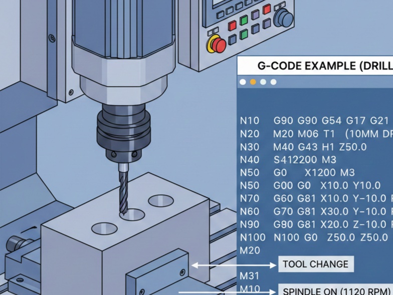
CNC (Computer Numerical Control) drilling cycles, commonly known as canned cycles, represent one of the most powerful features in G-code programming for milling machines. These pre-programmed sequences simplify the creation of repetitive hole-making operations, dramatically reducing programming time and code length while improving consistency, safety, and efficiency.
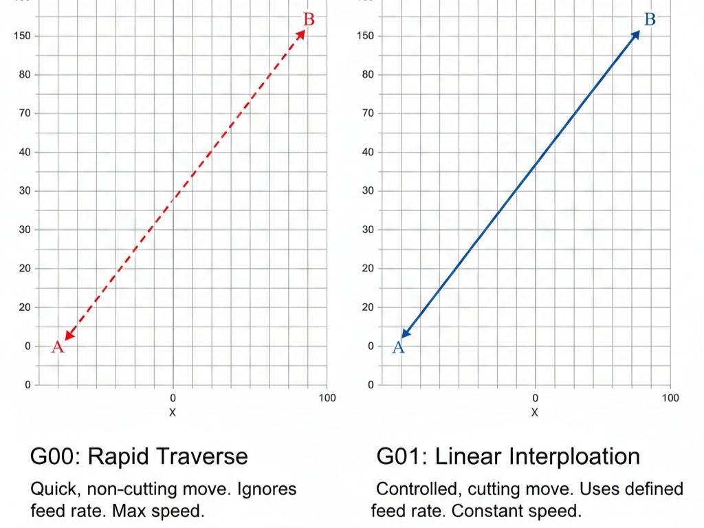
Instead of writing dozens or even hundreds of individual G00 and G01 moves for each hole (rapid positioning, feed to depth, retract, move to next hole), a single canned cycle block defines the entire behavior. The machine then automatically repeats the specified motion for every subsequent X/Y coordinate until the cycle is canceled with G80.
Most modern CNC controls (Fanuc, Haas, Siemens, Mitsubishi, etc.) support a standard set of drilling-related canned cycles, with G81, G82, and G83 being the most frequently used for general drilling tasks. This article explores these cycles in depth, including their syntax, motion sequences, applications, advantages, limitations, and practical programming examples.
1. Fundamental Parameters Common to All Drilling Canned Cycles
Before examining individual cycles, let’s understand the key parameters shared by most drilling cycles:
- X, Y → Hole location (absolute or incremental depending on G90/G91 mode). Optional if the spindle is already positioned over the first hole.
- Z → Final depth of the hole (usually negative in Z-down convention).
- R → Retract plane / reference plane. The Z-level to which the tool rapids down before feeding and rapids back to after each hole (typically 2–10 mm above the workpiece surface).
- F → Feedrate during the cutting portion (mm/min or in/min).
- P → Dwell time at bottom (in milliseconds, e.g., P1000 = 1 second). Used in some cycles.
- Q → Peck depth / cut increment. Critical for peck drilling cycles.
- L → Number of repetitions (rarely used today; mostly legacy).
Two important modal commands also affect behavior:
- G98 → Return to initial Z level after each hole (safer when holes are at different heights).
- G99 → Return to R plane after each hole (faster for holes on the same plane).
The cycle remains active until canceled with G80 or replaced by another canned cycle.
2. G81 – Standard Drilling Cycle (The Most Basic One)
Purpose: Simple drilling of shallow holes without chip breaking or special bottom actions.
Motion sequence:
- Rapid to X,Y position at initial Z height
- Rapid down to R plane
- Feed to Z depth at F rate
- Rapid retract to R plane (G99) or initial Z (G98)
- Move to next hole (if any)
Typical syntax:
G98 G81 X... Y... Z... R... F...   ; first hole
X... Y...                          ; second hole
X... Y...                          ; third hole
G80 ; cancel cycleApplications:
- Shallow holes (< 3× diameter)
- Spot drilling / center drilling
- Through holes in soft materials (aluminum, plastic, wood)
- When chips evacuate easily
Advantages:
- Fastest cycle for shallow work
- Very simple programming
- Minimal tool wear in easy materials
Limitations:
- No chip breaking → poor performance in deep holes or gummy materials (chips pack, tool breaks, poor finish)
Example (drilling 4 holes Ø10 mm, depth 12 mm):
G90 G54 G17 ; absolute, work offset, XY plane
T1 M06 ; tool change
S2000 M03 ; spindle on
G00 X20 Y20 Z50 ; safe position
G99 G81 Z-12 R2 F150 ; start cycle, return to R=2
X40 Y20
X40 Y40
X20 Y40
G80 ; end cycle
G00 Z50 ; retract
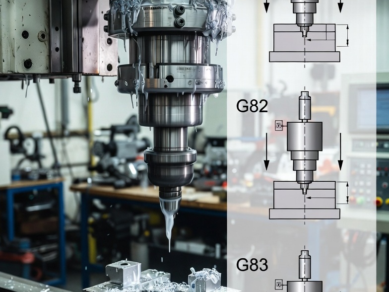
M05 M303. G82 – Drilling Cycle with Dwell (Counterboring / Spotface Cycle)
Purpose: Same as G81 but adds a programmed dwell at the bottom.
Motion sequence:
Identical to G81 except:
- Dwell for P time at Z depth (spindle keeps turning)
- Rapid retract
Typical syntax:
G82 X... Y... Z... R... P... F...Applications:
- Counterboring / spotfacing (flat bottom needed)
- When more accurate depth control is required (dwell helps break chip at bottom)
- Chamfering / light facing at hole entrance
Advantages:
- Better bottom finish
- More precise depth in blind holes
Limitations:
- Slightly slower than G81
- Still no chip breaking for deep holes
Example (counterboring with 0.5 s dwell):
G82 Z-8 R3 P500 F1204. G83 – Peck Drilling Cycle (Deep Hole Drilling)
Purpose: Deep hole drilling with automatic chip breaking.
Motion sequence:
- Rapid to X,Y and R plane
- Feed first peck distance (Q value)
- Rapid retract to R plane (clears chips)
- Rapid back down to previous depth minus a small clearance
- Feed next Q increment
- Repeat until Z depth is reached
- Final rapid retract to R or initial Z
Typical syntax:
G83 X... Y... Z... R... Q... F...Q parameter → peck increment (usually 2–10 mm depending on material/tool)
Applications:
- Deep holes (>3–5× diameter)
- Stainless steel, titanium, alloy steels
- Any material where chips tend to pack and cause tool breakage
Advantages:
- Excellent chip evacuation
- Reduced heat and tool wear
- Prevents drill breakage in deep holes
Limitations:
- Slower than G81/G82 (due to repeated retracts)
- More spindle on/off cycles (if using M08/M09)
Example (deep hole Ø8 mm, total depth 45 mm, peck 8 mm):
G83 Z-45 R3 Q8 F80Many controls allow decreasing peck depth as hole gets deeper (parameter setting).
5. Comparison Table: G81 vs G82 vs G83
| Feature | G81 (Standard) | G82 (Dwell) | G83 (Peck) |
|---|---|---|---|
| Peck / Chip break | No | No | Yes (full retract) |
| Dwell at bottom | No | Yes (P) | No |
| Best for depth | < 3× D | < 3–4× D | > 5× D (up to 20–30× D) |
| Speed | Fastest | Fast | Slowest |
| Chip evacuation | Poor | Poor | Excellent |
| Typical applications | Spot, shallow thru | Counterbore, blind | Deep holes, tough materials |
| Tool life in deep holes | Poor | Poor | Good |
6. Additional Notes and Best Practices
- Always use G99 for same-plane holes → saves time
- Use G98 when workpiece has different heights or clamps
- Peck value Q in G83: start conservative (4–8 mm), optimize based on material
- Many controls offer G73 (high-speed peck) – short retract only (faster than G83)
- For tapping → use G84 (right-hand) or rigid tapping variants
- For reaming/boring → G85 (feed out) or G89 (dwell + feed out)
- Always cancel with G80 before changing plane or tool
CNC drilling cycles transform complex hole patterns into elegant, reliable programs. G81 serves as the go-to for simple jobs, G82 adds precision for counterboring, and G83 is essential for deep, reliable drilling in demanding materials. Mastering these cycles, along with proper R-plane selection, peck values, and G98/G99 usage, significantly improves productivity, part quality, and tool life.
Understanding when to choose each cycle is a hallmark of experienced CNC programmers. Practice with simple parts, gradually increasing depth and material difficulty, and you’ll quickly appreciate why canned cycles remain one of the most valuable features of modern CNC controls.