Step Turning CNC Lathe Programming Guide with G-Code Example
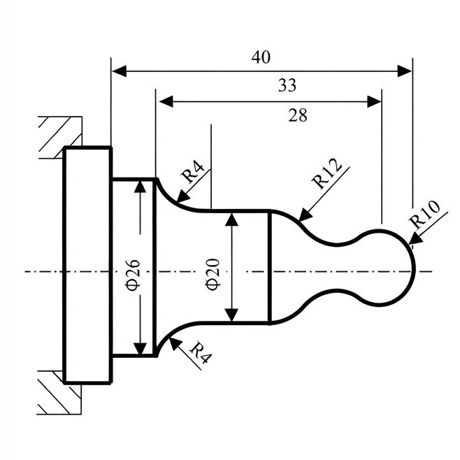
In step turning, different parts of a cylindrical workpiece are turned to different diameters. The finished component therefore includes two or more diameter or “steps”.
Step Turning CNC Lathe Programming Example
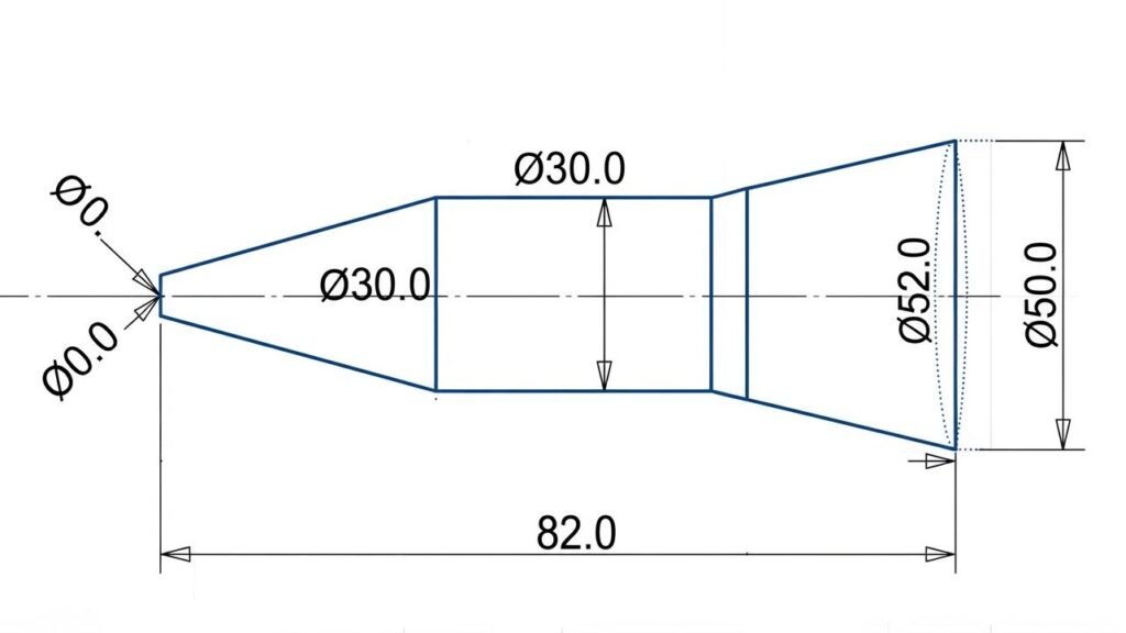
This program is for Step Turning / Taper Turning on a CNC Lathe. It will create a cylindrical job with a stepped profile with different diameters and a chamfer at the end.
In this case, the material will be rough removed with the G71 roughing cycle and then the final profile will be finished with the G70 finishing cycle.
Before running this program, be sure to check that your machine has X values for diameter programming, which is the case in most CNC lathes.
O1001
G21
G40 G99 G97
T0101
G50 S2500
G96 S180 M03
G00 X52.0 Z2.0 M08
G71 U2.0 R1.0
G71 P10 Q20 U0.5 W0.1 F0.25
N10 G00 X0.0
G01 Z0.0 F0.15
X30.0 Z-40.0
Z-80.0
X50.0 Z-82.0
N20 X52.0
G00 X100.0 Z100.0 M09
T0101
G96 S220 M03
G00 X52.0 Z2.0 M08
G70 P10 Q20
G00 X150.0 Z150.0 M05
M30
CNC Step Turning Program Explanation
- O1001
Program number O1001. - G21
Metric programming and all values are interpreted in millimeters. - G40 G99 G97
Cancels cutter compensation, selects feed per revolution, and cancels constant surface speed mode. - T0101
Select Tool 1, Offset 1 - G50 S2500
Maximum spindle speed to 2500 RPM when constant surface speed is used. - G96 S180 M03
Constant surface speed at 180 m/min, starts the spindle in the clockwise direction. - G00 X52.0 Z2.0 M08
Moves the tool rapidly to X52.0 and Z2.0 and safely approaches the workpiece. M08 Turns on coolant. - G71 U2.0 R1.0
Defines a G71 rough turning cycle with a 2.0 mm depth of cut and a 1.0 mm tool retract amount. - G71 P10 Q20 U0.5 W0.1 F0.25
Profile blocks from N10 to N20 are indicated. Leaves 0.5 mm stock in X and 0.1 mm stock in Z for finishing. The roughing feed rate is 0.25 mm/rev. - N10 G00 X0.0
N10 marks the beginning of the profile geometry. - G01 Z0.0 F0.15
Linear feed move to Z0.0, feed rate of 0.15 mm/rev. - X30.0 Z-40.0
Moves linearly to X30.0 and Z-40.0, creating the first tapered or angled section of the workpiece profile. - Z-80.0
Moving in the Z-axis to Z-80.0 and maintaining the X position, creating the straight part of the step. - X50.0 Z-82.0
Moves to X50.0 and Z-82.0, chamfer toward the larger diameter. - N20 X52.0
End of the programmed profile. The tool moves to X52.0. - G00 X100.0 Z100.0 M09
Retracts the tool to X100.0 Z100.0 and turns the coolant off. - T0101
Calls Tool 1 again with offset 01 for the finishing operation. - G96 S220 M03
Sets constant surface speed to 220 m/min and spindle clockwise. - G00 X52.0 Z2.0 M08
Rapidly positions the finishing tool at X52.0 Z2.0 and turns the coolant on. - G70 P10 Q20
Executes the G70 finishing cycle using the profile defined between blocks N10 and N20. - G00 X150.0 Z150.0 M05
Rapidly moves the tool to the safe position and stops the spindle. - M30
Ends the CNC program.