CNC Lathe Facing Program – Fanuc G Code Step by Step
Facing is a fundamental operation on a CNC lathe where the tool removes material from the end face of a workpiece to create a flat surface perpendicular to the spindle axis. This is often the first step in machining a part, as it establishes a reference surface for subsequent operations like turning or drilling. On Fanuc-controlled CNC lathes, facing can be programmed using basic linear interpolation commands (like G01) or canned cycles (such as G94 for simple facing or G72 for rough facing with multiple passes).
This guide will walk you through the process step by step, from understanding the basics to writing and explaining complete programs. We’ll assume a basic setup: a cylindrical workpiece, imperial units (inches), and a right-hand turning tool.
Step 1: Understand the Facing Operation
Before writing code, clarify what facing entails:
Objective: Cut across the face of the workpiece from the outer diameter toward the centerline (or slightly past to avoid a nub).
Tool Path: The tool starts at a safe position above the face (positive Z) and outside the diameter (positive X). It rapids into position, feeds inward along the X-axis while holding Z constant, then retracts.
Key Parameters:
Spindle Speed (S): Based on material and tool (e.g., S500 for mild steel).
Feed Rate (F): Typically 0.005–0.015 inches per revolution (IPR) for finishing.
Depth of Cut: For roughing, 0.05–0.1 inches per pass; for finishing, lighter cuts.
Coolant: Use M08 to turn on flood coolant for better chip evacuation and tool life.
Coordinates: On a lathe, X is diameter (twice the radius), Z is along the spindle axis. Positive Z is away from the chuck.
Safety Considerations: Always include spindle limits (G50), tool offsets, and home commands. Simulate the program in the control or software to avoid crashes.
Facing can be done in one pass for thin cuts or multiple passes for thicker material removal.
Step 2: Review Essential G-Codes and M-Codes for Facing
Fanuc lathes use G-codes for motion and cycles, M-codes for machine functions. Here’s a quick reference for facing:
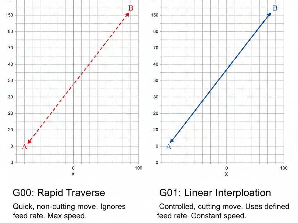
G00: Rapid traverse (non-cutting move).
G01: Linear interpolation (straight-line feed for cutting).
G21/G20: Metric (mm) or inch mode.
G94: Facing cycle (end face grooving/facing, feeds in Z while moving in X).
G72: Rough facing cycle (multi-pass, follows a contour if needed).
G96/G97: Constant surface speed (CSS) or RPM mode.
G50: Spindle speed clamp.
M03/M04: Spindle on clockwise/counterclockwise.
M08/M09: Coolant on/off.
Txxxx: Tool selection and offset (e.g., T0101 for tool 1, offset 1).
G28: Return to reference point.
Programs start with a program number (Oxxxx), end with M30, and use N-numbers for line labels. Always program in absolute mode (G90) for simplicity unless incremental (G91) is needed.
Step 3: Set Up the Program Structure
A typical Fanuc lathe program follows this flow:
Header: Program number, units, and initial setup.
Tool Change: Select tool and set offsets.
Spindle and Coolant: Start rotation and coolant.
Positioning: Rapid to start point.
Cutting: Perform the facing passes.
Retract and Shutdown: Stop spindle, coolant, and end program.
Use G99 (feed per revolution) for lathe work to maintain consistent chip load.
Step 4: Simple Facing Program Using G01 (Manual Passes)
For a basic single-pass or manual multi-pass facing, use G00 for positioning and G01 for cutting. This is ideal for simple jobs without needing cycles.
Example Scenario
- Workpiece: 2-inch diameter bar, face off 0.1 inches from Z=0.
- Tool: Right-hand facing tool.
- Spindle: 1200 RPM, clockwise.
- Feed: 0.01 IPR.
- Cut from X=2.2 to X=-0.06 (past centerline).
Sample Program
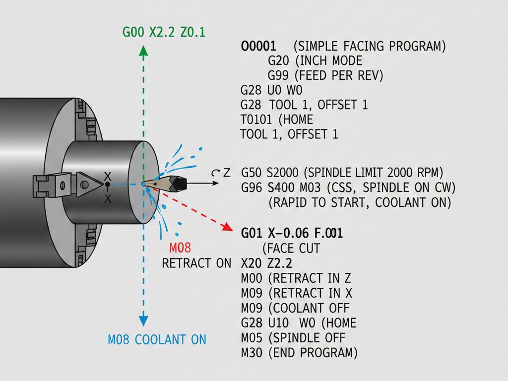
O0001 (SIMPLE FACING PROGRAM)
G20 (INCH MODE)
G99 (FEED PER REV)
G28 U0 W0 (HOME)
T0101 (TOOL 1, OFFSET 1)
G50 S2000 (SPINDLE LIMIT 2000 RPM)
G96 S400 M03 (CSS 400 SFM, SPINDLE ON CW)
G00 X2.2 Z0.1 M08 (RAPID TO START, COOLANT ON)
G01 X-0.06 F0.01 (FACE CUT)
G00 Z0.2 (RETRACT IN Z)
X2.2 (RETRACT IN X)
M09 (COOLANT OFF)
G28 U0 W0 (HOME)
M05 (SPINDLE OFF)
M30 (END PROGRAM)O0001: Program identifier.
G20: Sets inches (use G21 for mm).
G99: Feed in IPR.
G28 U0 W0: Returns axes to home (U and W are incremental for X and Z).
T0101: Calls tool 1 with offset 1 (assumes offsets are set in the control).
G50 S2000: Clamps max spindle speed for safety.
G96 S400 M03: Constant surface speed at 400 feet per minute, spindle clockwise.
G00 X2.2 Z0.1 M08: Rapids to 0.1 inches above face, outside diameter; coolant on.
G01 X-0.06 F0.01: Feeds inward to past centerline at 0.01 IPR.
G00 Z0.2 / X2.2: Retracts safely.
M09 / G28 / M05 / M30: Shuts down and ends.
For multiple passes (e.g., three cuts of 0.033 inches each in Z), add loops or repeat the G01 lines with decreasing Z (e.g., Z0.067, Z0.033, Z0).
Step 5: Facing Using G94 Cycle (Single or Multi-Pass End Face Cycle)
G94 is a canned cycle for facing or end grooving. It allows multiple Z-cuts while feeding in X. It’s efficient for flat facing with consistent depth.
G94 Format (Two-Line Version for Fanuc)
- First line: G94 X__ Z__ F__ (X is end point, Z is depth per pass if looping).
- It repeats until canceled by G00.
Example Scenario
- Face a 65mm diameter part to 82mm long (but we’ll face the end).
- Three passes: Z2, Z1, Z0.
- Feed 0.2 mm/rev.
Sample Program
O0002 (G94 FACING EXAMPLE)
G21 (METRIC MODE)
G99 (FEED PER REV)
G28 U0 W0
T0101
G50 S1500
G96 S180 M03
G00 X66 Z3 M08 (START POSITION)
G94 X-1.6 Z2 F0.2 (FIRST PASS TO Z2)
Z1 (SECOND TO Z1)
Z0 (THIRD TO Z0)
G00 X100 Z100 (CANCEL CYCLE, RETRACT)
M09
G28 U0 W0
M05
M30Setup: Similar to before, but metric (G21).
Positioning: G00 to X66 (slightly over diameter) Z3 (above face).
G94 X-1.6 Z2 F0.2: Starts cycle: Feeds to X-1.6 (past center) at Z=2, feed 0.2 mm/rev.
Z1 / Z0: Subsequent lines adjust Z depth; cycle repeats the X motion.
G00: Cancels G94 and retracts.
Shutdown: As before.
This saves code compared to manual G01 for multi-passes. Note: G94 stays active until G00/G01/G02/G03 cancels it.
Step 6: Rough Facing Using G72 Cycle (Multi-Pass Contour Following)
For roughing complex faces or stepped profiles, use G72. It’s a two-block cycle that roughs parallel to the X-axis, retracting after each cut.
G72 Format (Two-Line)
- G72 W__ R__ (W=depth of cut in Z, R=retract amount).
- G72 P__ Q__ U__ W__ F__ (P=start block, Q=end block, U=X allowance, W=Z allowance, F=feed).
The contour is defined between N(P) and N(Q).
Example Scenario
- Rough face with profile: Start at Z1, cut to Z0, then contour.
- Depth of cut: 0.8mm per pass.
- Retract: 2mm.
- Finishing allowance: 1mm in X, 0.5mm in Z.
Sample Program
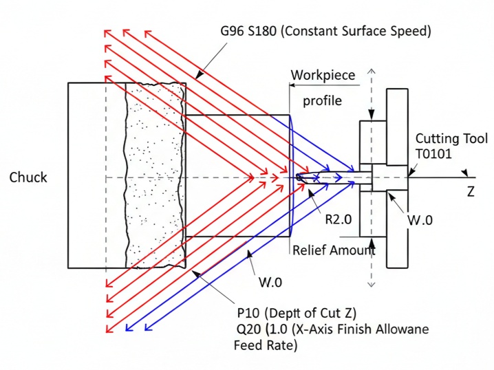
O0003 (G72 ROUGH FACING)
G21
G99
G28 U0 W0
T0101
G50 S1500
G96 S180 M03
G00 X50 Z2 M08
G72 W0.8 R2.0
G72 P10 Q20 U1.0 W0.5 F0.2
N10 G00 Z1.0
G01 X20.0 Z-0.5
N20 G01 X10.0 Z-1.0
G00 X100 Z100
M09
G28 U0 W0
M05
M30
Setup and Positioning: As before.
G72 W0.8 R2.0: Defines depth (0.8mm per pass), retract (2mm).
G72 P10 Q20 U1.0 W0.5 F0.2: Calls cycle from N10 to N20, leaves allowance for finish, feed 0.2.
Contour Definition (N10-N20): Describes the final profile (e.g., step down).
Cycle Behavior: Machine takes cuts parallel to X, retracts, steps in Z by W, repeats until contour reached.
Finish: Often follow with G70 finishing cycle (not shown here).
G72 is great for efficiency in roughing but requires defining the contour accurately.
Step 7: Advanced Tips and Troubleshooting
- Tool Compensation: Use G41/G42 for cutter radius comp if needed, but for simple facing, it’s often unnecessary.
- Simulation: Always dry-run or use graphics mode on the Fanuc control.
- Common Errors:
- Forgetting to cancel cycles (leads to unexpected moves).
- Incorrect units (G20 vs. G21).
- Spindle not starting (missing M03).
- Optimization: Use G96 for CSS to maintain cutting speed as diameter changes.
- Variations: For threading or other ops post-facing, chain programs.
- Software Aids: Use CAM like Fusion 360 to generate code, then hand-edit for Fanuc.
This covers the essentials for facing on a Fanuc CNC lathe. Practice on scrap material, and adjust parameters based on your machine, tool, and workpiece. If you have a specific part drawing or parameters, provide details for a customized program.