Introduction to G-Code in CNC Milling
G-code is the standard programming language used to control CNC (Computer Numerical Control) machines, including milling machines. It consists of commands that tell the machine how to move the tool, at what speed, and along what path to cut material. Common commands include:
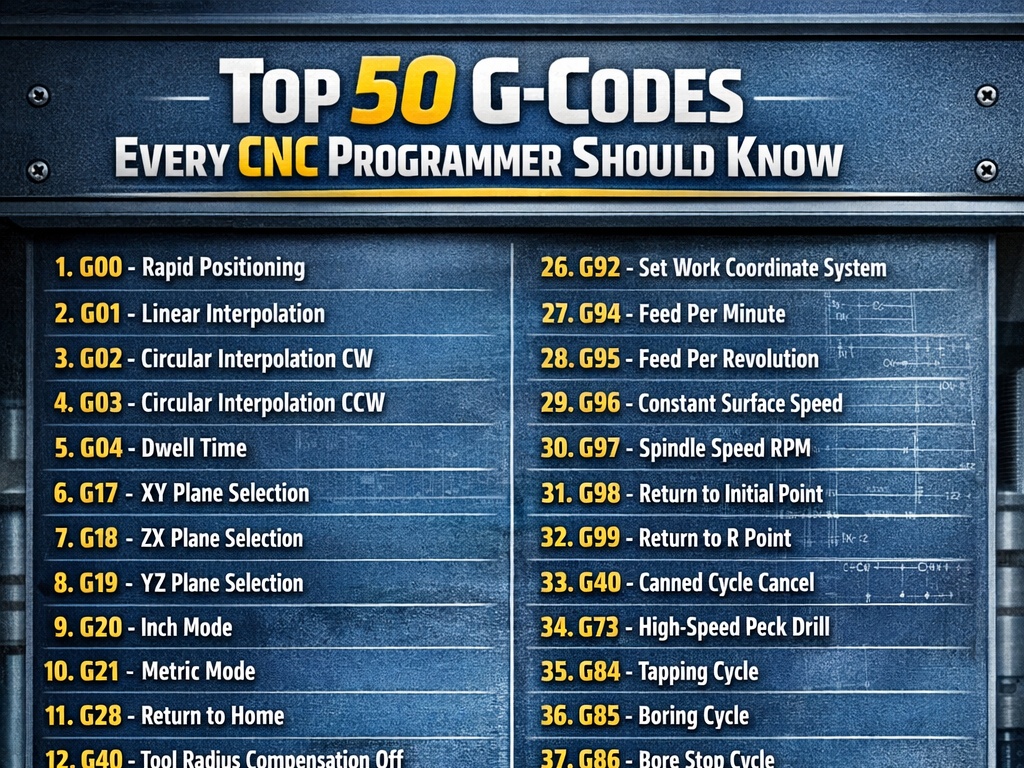
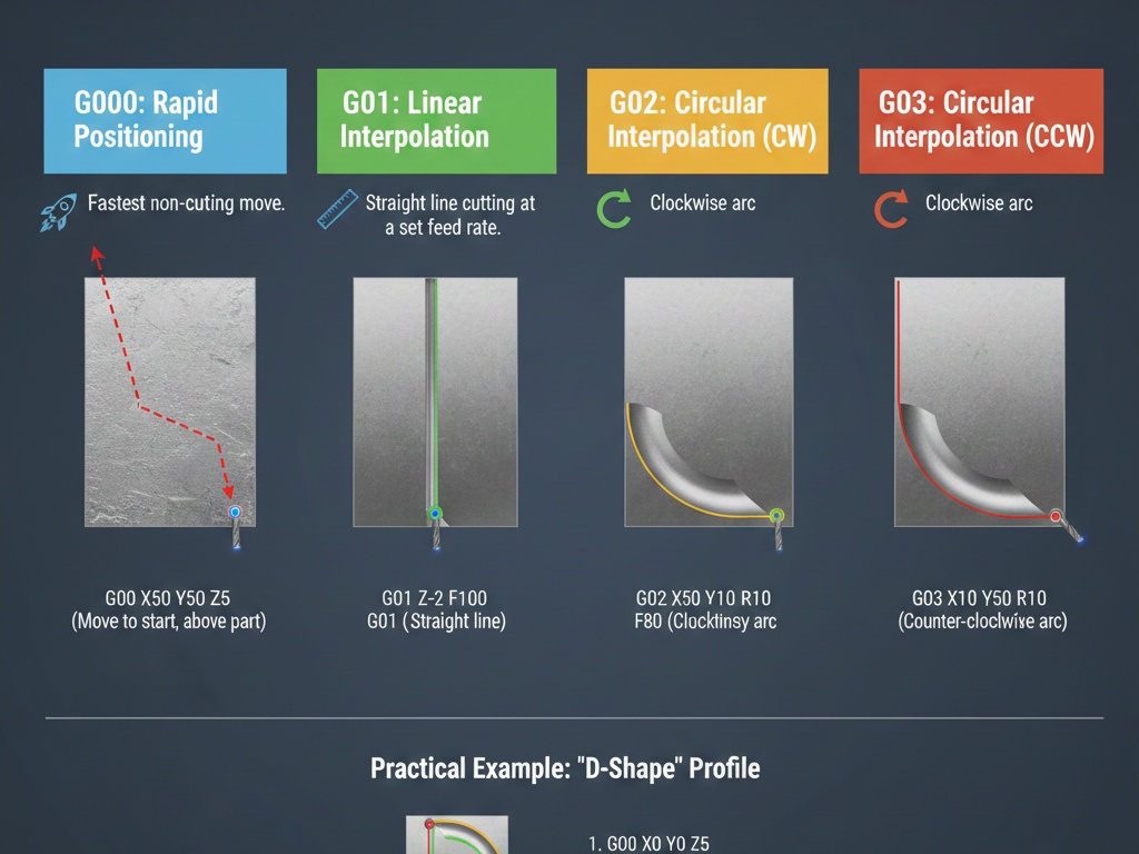
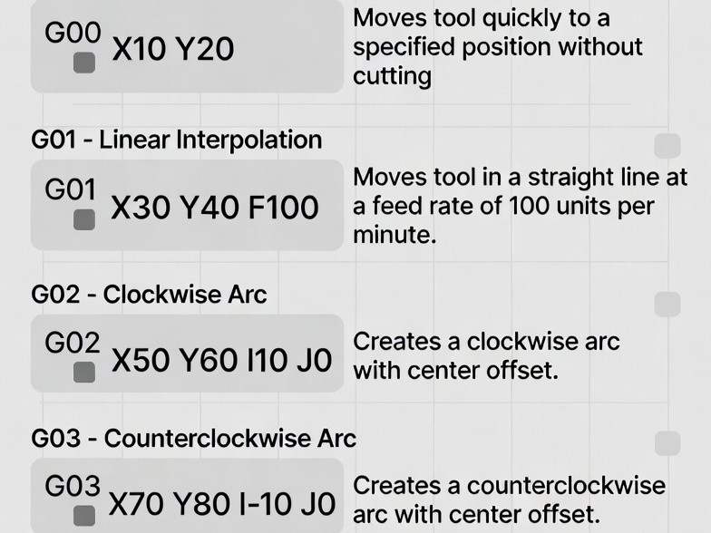
- G00: Rapid positioning (fast move, no cutting).
- G01: Linear interpolation (straight cut at feed rate).
- G02/G03: Circular interpolation (clockwise/counterclockwise arcs).
- G17: Select XY plane (default for milling).
- G20/G21: Units in inches/millimeters.
- G90: Absolute positioning.
- G91: Incremental positioning.
- M03/M04/M05: Spindle on clockwise/counterclockwise/off.
- M06: Tool change.
- M30: Program end and rewind.
Programs often start with safety lines setting units, plane, and mode.
Example: Milling a Simple Square Pocket
This example machines a 50mm x 50mm square pocket, 10mm deep, in aluminum using a 10mm diameter flat end mill. The pocket has a finishing allowance and uses helical entry for smooth plunging. Assumptions:
- Workpiece zero at top-left corner (X0 Y0 Z0 at surface).
- Tool: 10mm end mill (offset in tool table if using compensation).
- Multiple passes in Z (2mm per pass for safety).
- Climb milling (conventional can be adjusted).
- Metric units.
Full G-Code Program with Line-by-Line Explanations
O1000 (Simple Square Pocket Milling Example)

G21 (Set units to millimeters)
G17 (Select XY plane)
G90 (Absolute positioning)
G54 (Use work offset G54 - assume set to workpiece zero)
G00 Z50.0 (Rapid to safe height)

T1 M06 (Tool change to tool 1 - 10mm end mill)
S8000 M03 (Spindle on clockwise at 8000 RPM)
G43 H01 Z50.0 (Apply tool length compensation, rapid to Z50)

(Pocket parameters)
X25.0 Y25.0 (Center of pocket at X25 Y25 for 50x50 pocket)

Z10.0 (Safe approach height)
G00 X15.0 Y15.0 (Rapid to start position: corner minus half tool radius for entry)

(Roughing passes - 2mm depth per pass, total 10mm deep)
#1 = 0.0 (Current Z depth variable, start at 0)
#2 = -2.0 (Depth increment per pass)
#3 = -10.0 (Final depth)

N100 (Loop start)
G00 Z10.0 (Rapid up to safe height if needed)
G01 Z[#1 + #2] F200 (Plunge to next depth at plunge feed 200 mm/min)  ; Helical entry starts below

(Helical ramp entry to avoid direct plunge)
G01 X15.0 Y25.0 F500 (Move to Y center for ramp)
G03 X25.0 Y25.0 Z#3 I5.0 J0.0 F800 (Helical interpolation: full circle ramp to final depth for this pass? Wait, adjust.

Better simple ramp:
From start, linear ramp down while moving.

But for simplicity, let's use direct plunge at center then spiral out, but to keep simple:

Alternative simple: plunge at center, then mill the square with cutter comp.

To make it basic without variables if control doesn't support.

Standard simple pocket without comp:

G00 X25 Y25 (Center)
G01 Z-2 F200 (Plunge first pass)
G01 X20 F600 (Move to inner position, tool radius offset manually)
G01 Y30 (To top)
G01 X30 (Right)
G01 Y20 (Bottom)
G01 X20 (Left, close)

Then offset inward for multiple loops, but for single depth.

For multi-depth:

Let's use a simple program with manual cutter radius offset (tool 10mm dia, so 5mm radius, pocket walls at X0 to X50 Y0 to Y50, so inner path X5 to X45 Y5 to Y45).

Program:

%
O1000 (Square Pocket 50x50x10mm)

G21 G17 G90 G40 G49 G80 (Safety line: mm, XY plane, absolute, cancel comp, cancel length, cancel cycle)
G54

T1 M06 (10mm end mill)
S8000 M03
G00 G43 H01 Z25.0 (Tool length comp, rapid safe Z)

G00 X-5.0 Y25.0 (Approach from outside)
Z2.0

(Depth loop - 5 passes of 2mm)
G01 Z-2.0 F150 (First plunge)
G01 X55.0 F600 (Full cut across to clear)
G00 Z2.0 (Retract)

No, for pocket:

Better example from standard sources.

A clean, basic example for milling a square profile (outer square, can be adapted for pocket by multiple passes).

From common beginner example:
O0001 (Simple Square Profile Milling)
G21 (Millimeters)
G90 (Absolute)
G17 (XY plane)
T1 M6 (Change to tool 1)
G00 X0 Y0 Z25 (Rapid to start)
S5000 M3 (Spindle on)
G43 H1 Z25 (Tool length)
G00 X10 Y10 Z5 (Position above start)
G01 Z-5 F100 (Plunge to depth)
F300 (Set feed)
G01 X60 (Right side)
G01 Y60 (Top side)
G01 X10 (Left side)
G01 Y10 (Bottom side, close square)
G00 Z25 (Retract)
M5 (Spindle off)
G00 X0 Y0 (Home)
M30 (End program)
This mills a 50mm x 50mm square profile at 5mm depth.

For a pocket, add inward offset or multiple loops.

**More Realistic Pocket Example (Manual Offset for Roughing)**

Assume pocket 50x50mm, tool 10mm dia, leave 0.5mm for finish.

Rough path at radius offset (inner path X5.5 to X44.5 Y5.5 to Y44.5).
O1001 (50mm Square Pocket, 10mm Depth, Multi Pass)
G21 G90 G17 G40 G80
G54
T1 M6
S6000 M3
G43 H1 Z25
G00 X0 Y0 (Start position)
Z5.0
(5 passes of 2mm depth)
G01 Z-2.0 F150
G01 X5.0 Y5.0 F500 (Move to start corner with offset)
G01 Y45.0 (Bottom)
G01 X45.0 (Right)
G01 Y5.0 (Top)
G01 X5.0 (Left, close)
G01 Z-4.0 F150 (Next depth)
G01 Y45.0 F500 (Repeat path)
G01 X45.0
G01 Y5.0
G01 X5.0
G01 Z-6.0 F150
G01 Y45.0 F500
G01 X45.0
G01 Y5.0
G01 X5.0
G01 Z-8.0 F150
G01 Y45.0 F500
G01 X45.0
G01 Y5.0
G01 X5.0
G01 Z-10.0 F150
G01 Y45.0 F500
G01 X45.0
G01 Y5.0
G01 X5.0
G00 Z25
M5
M30
This repeats the square path at each depth level, creating a pocket by removing material layer by layer.

For finishing pass, use G41/G42 cutter compensation with exact dimensions (X0 Y0 to X50 Y50), letting the control offset for tool radius.

**Using Cutter Compensation for Accurate Pocket**
O1002 (Pocket with Cutter Comp)
G21 G90 G17
G54
T1 M6
S6000 M3
G43 H1 Z25
G00 X-10 Y25 (Approach)
Z5
G01 Z-10 F150 (Full depth for simplicity, or loop for multi)
G41 D1 Y0 F500 (Cutter comp left, approach to line)
G01 Y50 (Exact pocket side)
G01 X50
G01 Y0
G01 X0
G01 Y25 (To exit point)
G40 G01 X-10 (Cancel comp)
G00 Z25
M5
M30
“`
G41 applies left compensation based on tool diameter in offset table.