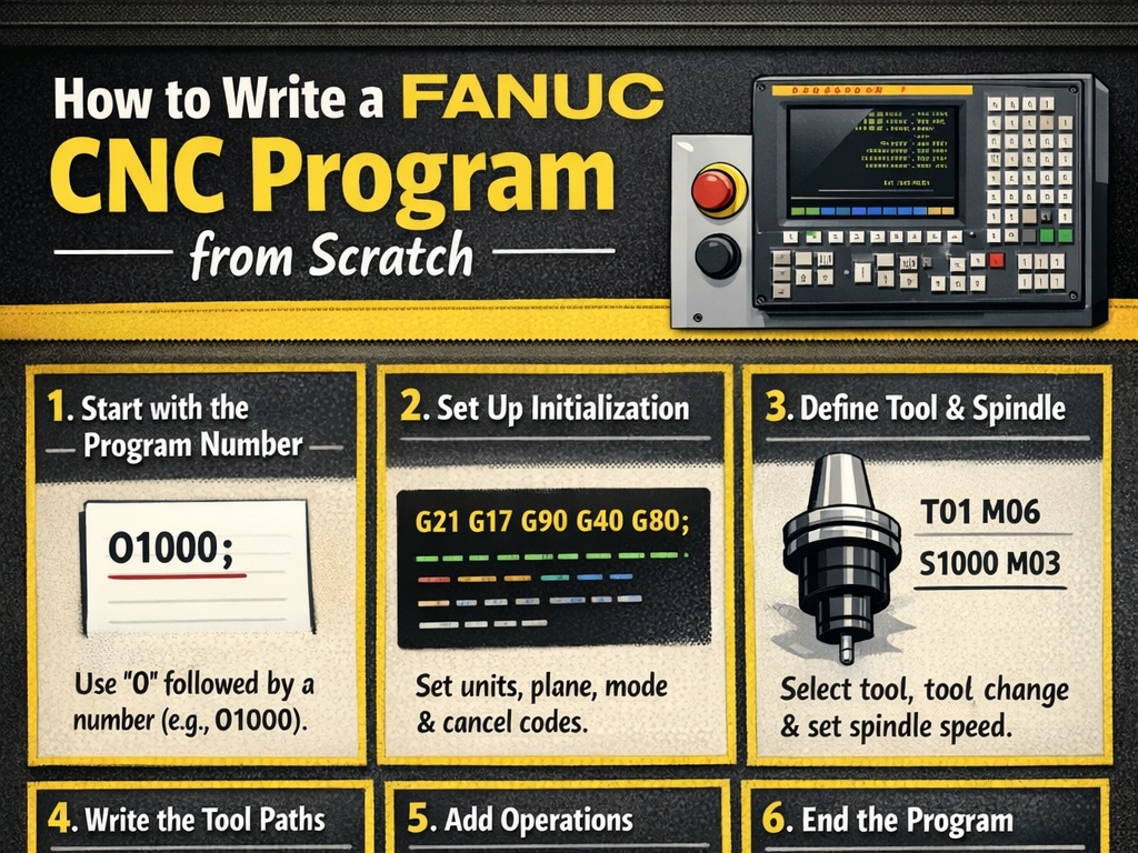
How to Write a Fanuc CNC Program from Scratch
Fanuc CNC systems are among the most widely used controllers in the world for both milling machines and lathes. Writing a Fanuc CNC program from scratch involves understanding the basic structure, key commands (G-codes and M-codes), coordinate systems, and safety practices. This guide will walk you through the process step by step, focusing on manual programming (hand-written G-code) for beginners. We’ll cover the fundamentals applicable to both turning (lathes) and milling, with examples.
Fanuc programs use ISO-standard G-code format, where each line (called a “block”) contains commands that tell the machine how to move, cut, or perform auxiliary functions. Programs are typically written in a text editor or directly on the machine’s control panel.
Step 1: Understand the Basic Program Structure
Every Fanuc program follows a consistent structure:
- Program Number: Starts with
Ofollowed by a 4-digit number (e.g.,O0001). This is the program’s identifier. - Safety and Setup Lines: Initial commands for units, modes, work offsets, and home positioning.
- Main Body: Tool changes, movements, cutting operations.
- Program End: Stops spindle, coolant, and rewinds.
A basic template looks like this:
O0001 (PROGRAM NAME OR DESCRIPTION)
% (Optional start delimiter, some systems use it)
G21 (Metric units) or G20 (Inch units)
G17 (XY plane selection for milling)
G40 (Cancel tool compensation)
G49 (Cancel tool length compensation)
G80 (Cancel canned cycles)
G90 (Absolute positioning)
G54 (Work offset selection)
T01 M06 (Tool change to tool 1)
S2000 M03 (Spindle speed 2000 RPM, clockwise)
G43 H01 Z50.0 (Tool length compensation, rapid to safe height)

(Main machining blocks here)

G00 Z50.0 (Retract to safe height)
M05 (Spindle stop)
M09 (Coolant off)
M30 (Program end and rewind)
%
Each block ends with a semicolon (;) on some controls, but modern Fanuc often uses line feeds.
Step 2: Key Concepts Before Writing Code
- Coordinate Systems:
- Absolute (G90): Positions relative to a fixed origin (e.g., G54 work offset).
- Incremental (G91): Positions relative to the current tool location.
- Motion Types:
- Rapid (G00): Fast non-cutting move.
- Linear Feed (G01): Straight cut at specified feed rate (F).
- Circular (G02/G03): Arcs (clockwise/counterclockwise).
- Planes: G17 (XY), G18 (XZ), G19 (YZ) – important for milling arcs.
- Units: G20 (inches), G21 (mm).
- Feed and Speed: F for feed rate (mm/min or ipm), S for spindle RPM.
Always start in a safe position (e.g., tool retracted high above the part).
Step 3: Common G-Codes (Preparatory Codes)
G-codes prepare the machine for motion or modes. Here are the most essential for Fanuc:
- G00: Rapid positioning.
- G01: Linear interpolation (cutting feed).
- G02: Circular interpolation clockwise.
- G03: Circular interpolation counterclockwise.
- G17/G18/G19: Plane selection.
- G20/G21: Inch/Metric.
- G28: Return to machine home/reference.
- G40/G41/G42: Tool radius compensation (off/left/right).
- G43/G49: Tool length compensation (positive/ cancel).
- G54-G59: Work coordinate offsets.
- G80: Cancel canned cycle.
- G90/G91: Absolute/Incremental.
- Canned Cycles (Milling): G81 (drill), G83 (peck drill), G84 (tap).
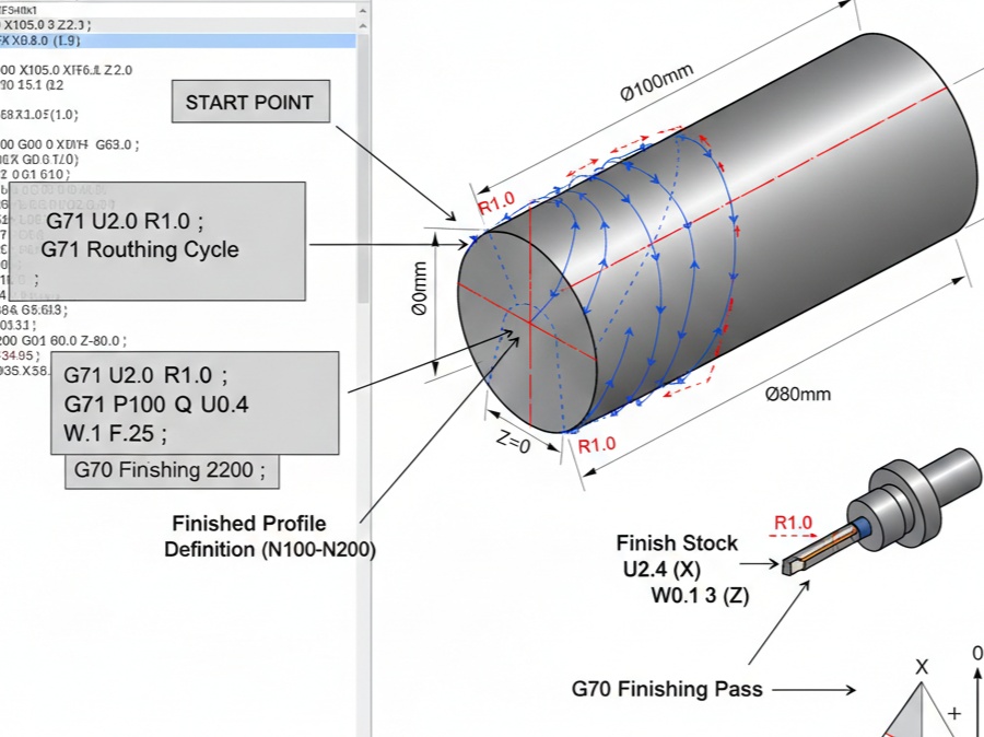
- Canned Cycles (Lathe): G71 (rough turning), G70 (finish), G76 (threading).
Step 4: Common M-Codes (Miscellaneous Codes)
M-codes control machine functions:
- M00: Program stop.
- M01: Optional stop.
- M03: Spindle on clockwise.
- M04: Spindle on counterclockwise.
- M05: Spindle stop.
- M06: Tool change.
- M08: Coolant on.
- M09: Coolant off.
- M30: Program end and rewind.
Step 5: Creating a Program on the Fanuc Control
- Power on the machine and home all axes (usually via buttons on the panel).
- Switch to EDIT mode.
- Press PROGRAM key.
- Create new: Press O, enter number (e.g., 0001), then INSERT or CREATE.
- Write blocks line by line using the keyboard.
- Insert comments in parentheses, e.g., (FACE MILL TOP SURFACE).
- Save and verify syntax.
- Test in graphics simulation mode before running.
Step 6: Example Program – Simple Milling Operation
Let’s write a basic program for milling a rectangular pocket on a Fanuc mill.
Assume: 10mm end mill, material aluminum, part zero at top center.
O1001 (RECTANGULAR POCKET EXAMPLE)
G21 G17 G40 G49 G80 G90 (Setup: Metric, XY plane, cancel compensations, absolute)
G54 (Work offset)
T1 M06 (Tool 1: 10mm end mill)
S5000 M03 (Spindle 5000 RPM CW)
G00 X0 Y0 Z50.0 (Rapid to center safe height)
G43 H01 Z5.0 (Apply tool length comp, approach)
G01 Z-5.0 F200 (Plunge to depth at feed)
G01 X50.0 Y50.0 F500 (Linear move to corner)
G01 X-50.0 (To opposite X)
G01 Y-50.0 (To opposite Y)
G01 X50.0 (Close rectangle)
G00 Z50.0 (Retract)
M05 M09 (Spindle and coolant off)
G28 Z0 (Home Z axis)
M30 (End program)
This is a rough outline – real programs include multiple passes for depth.
Step 7: Example Program – Simple Turning Operation (Lathe)
For a basic OD turning on a Fanuc lathe:
O2001 (SIMPLE TURNING EXAMPLE)
G21 G18 G40 G80 G90 (Metric, XZ plane)
G50 S3000 (Max spindle speed limit)
G96 S200 M03 (Constant surface speed 200 m/min, CW)
T0101 (Tool 1 with offset 1)
G00 X50.0 Z5.0 (Rapid approach)
G71 U2.0 R1.0 (Rough cycle: depth 2mm, retract 1mm)
G71 P10 Q20 U0.5 W0.2 F0.3 (Allowances, feed)
N10 G00 X0 (Start contour)
G01 Z0
G01 X20.0 Z-10.0
G01 Z-50.0
N20 G01 X50.0 (End contour)
G00 X100.0 Z50.0 (Retract)
G28 U0 W0 (Home)
M05 M09
M30
Step 8: Best Practices and Safety
- Always simulate the program graphically on the control.
- Use dry runs (no coolant, tool above part).
- Include safe retracts (high Z).
- Comment extensively.
- Start slow: Low feeds/speeds for first runs.
- Verify tool offsets and work offsets.
- For complex parts, consider CAM software to generate code, then edit manually.
Step 9: Advanced Topics
Once basics are mastered:
- Canned cycles for efficiency.
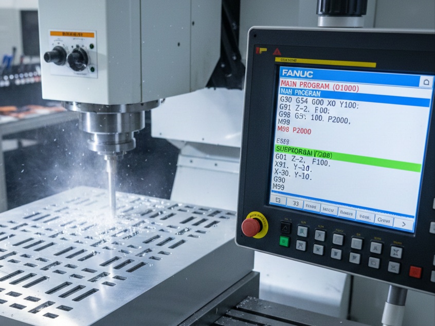
- Subprograms (M98/M99) for repeating features.
- Macro programming (variables, loops) for families of parts.
- Probe cycles for in-machine measurement.
Practice on existing programs: Load sample programs, run them, and modify.
Writing Fanuc programs from scratch builds deep understanding and troubleshooting skills. Start simple, verify every step, and gradually tackle complex parts. With practice, you’ll produce efficient, safe code. Resources like Fanuc manuals or online simulators can help reinforce these concepts.