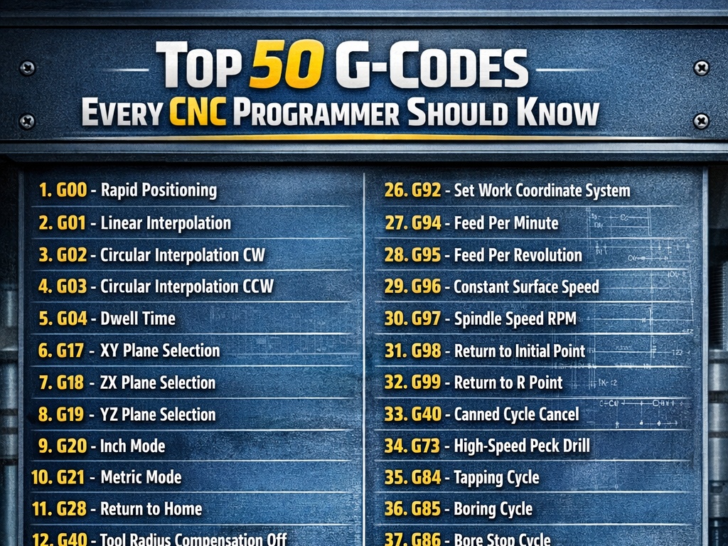
G00, G01, G02, G03 Explained With Examples
In the world of CNC (Computer Numerical Control) machining, G-codes are the language that tells a machine exactly how to move. While there are hundreds of codes, the “Big Four”—G00, G01, G02, and G03—handle about 90% of all motion commands.
Understanding these is the difference between a perfectly machined part and a broken tool.
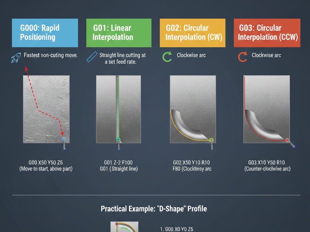
1. G00: Rapid Positioning
G00 is used to move the tool from point A to point B as fast as the machine can possibly go. It is non-cutting motion.
Think of G00 as the “teleport” command. You use it to move the tool to the start of a cut or to retract it safely away from the part.
Key Characteristics
- Speed: Uses the machine’s maximum “rapid” traverse rate (pre-set by the manufacturer).
- Pathing: In many older machines, G00 doesn’t move in a straight line; it moves all axes at max speed, often resulting in a “dog-leg” motion.
- Precision: It is not for interpolation. Never use G00 while the tool is touching the material.
Example Code:
G00 X50.0 Y50.0 Z5.0
(The tool will rush to these coordinates at maximum speed, stopping 5mm above the workpiece.)
2. G01: Linear Interpolation
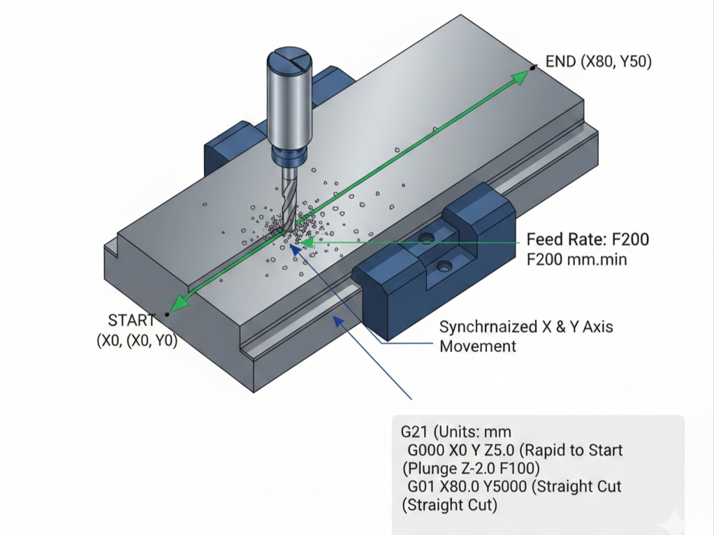
G01 is the workhorse of CNC machining. It tells the machine to move in a straight line at a specific speed, known as the Feed Rate (F).
Unlike G00, G01 is used for actual cutting (milling a slot, facing a surface, or turning a diameter).
Key Characteristics
- Controlled Speed: Requires an
Fcommand (e.g.,F100for 100mm/min). - Straight Path: The machine calculates the synchronized movement of all axes to ensure a perfectly straight line.
Example Code:
G01 Z-5.0 F150 (Plunge into the material at 150mm/min)
G01 X100.0 Y0.0 (Cut a straight line to X100)
3. G02: Circular Interpolation (Clockwise)
G02 tells the tool to move in a clockwise arc. To create a curve, the machine needs more than just a destination; it needs to know the radius or the center point of the arc.
How to Define the Arc
There are two common ways to program a G02:
- R-Command: Specify the destination and the Radius.
G02 X20.0 Y20.0 R10.0 F100
- I, J, K Commands: Specify the distance from the start point to the center of the circle.
I= X-axis offsetJ= Y-axis offset
4. G03: Circular Interpolation (Counter-Clockwise)
G03 functions exactly like G02, but the tool moves in a counter-clockwise direction. This is frequently used for pocket milling or “climb milling” on the outside of a part.
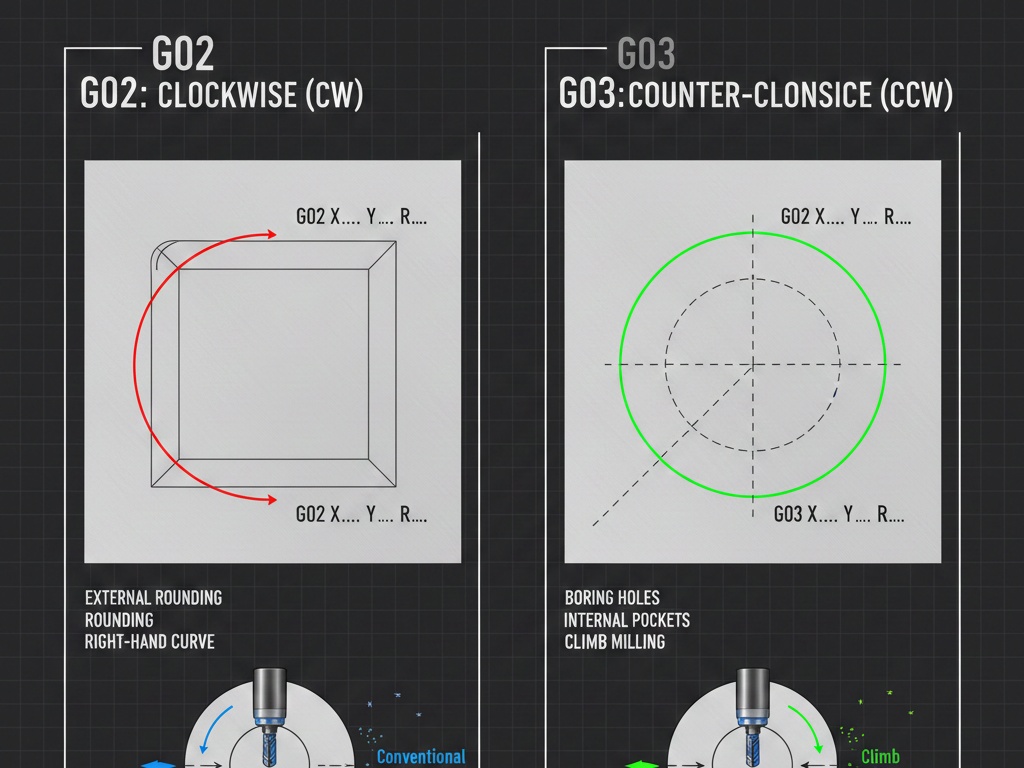
Comparison Table: G02 vs G03
| Command | Direction | Typical Use |
| G02 | Clockwise (CW) | External rounding, right-hand curves |
| G03 | Counter-Clockwise (CCW) | Boring holes, internal pockets, climb milling |
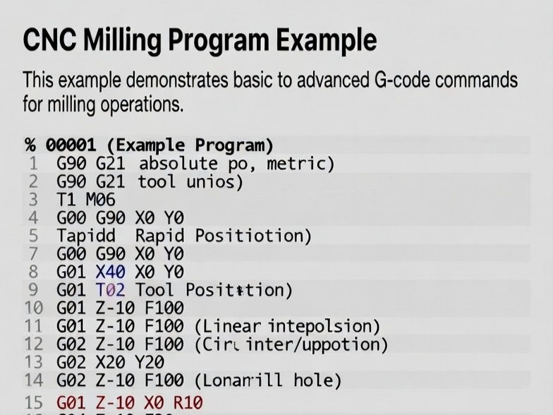
Putting It All Together: A Sample Program
Imagine we are cutting a simple 50mm square with a rounded corner.

- G00 X0 Y0 Z5.0 (Rapid to start position, above the part)
- G01 Z-2.0 F100 (Feed down into the material)
- G01 X40.0 Y0 (Cut a straight line 40mm long)
- G02 X50.0 Y10.0 R10.0 (Cut a 10mm clockwise arc/corner)
- G01 Y50.0 (Continue straight line up)
- G00 Z10.0 (Rapid retract out of the part)
Summary Checklist
- G00: Fast movement, no cutting.
- G01: Straight line cutting (needs a Feed rate).
- G02: Clockwise curves.
- G03: Counter-clockwise curves.