G & M Codes with Examples
G-codes and M-codes form the foundation of CNC (Computer Numerical Control) programming, a language that instructs CNC machines like mills, lathes, and routers on how to move and operate. Developed in the 1950s at MIT and standardized as RS-274 (now ISO 6983), G-code primarily controls geometry—tool paths, movements, and coordinates—while M-code handles miscellaneous or machine functions like spindle control, coolant, and program flow.
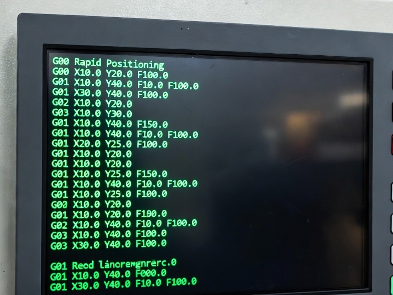
These codes are modal (they remain active until canceled or changed) and appear in blocks (lines) of a program. A typical block might look like: N10 G01 X50.0 Y25.0 F200 (line number, linear move to coordinates at feed rate 200). Most modern programs are generated by CAM software, but understanding manual coding helps with editing, troubleshooting, and optimization.
While standards exist, variations occur across controllers (e.g., Fanuc, Haas, Siemens). Always consult your machine’s manual.
Common G-Codes: Motion and Geometry Control
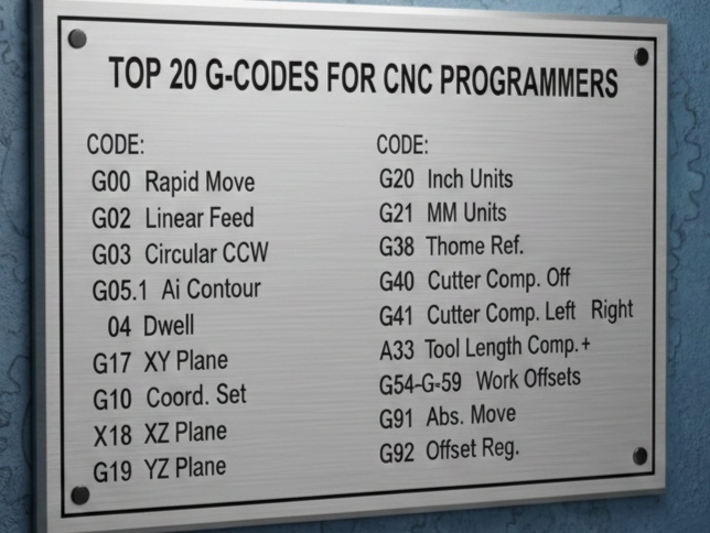
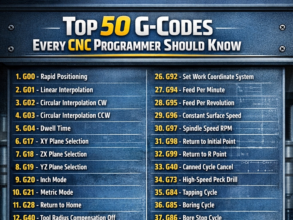
G-codes dictate tool movement. Here are the most frequently used, with descriptions and examples (primarily for milling; lathes use similar but with U/W for incremental axes).
| G-Code | Description | Example | Explanation |
|---|---|---|---|
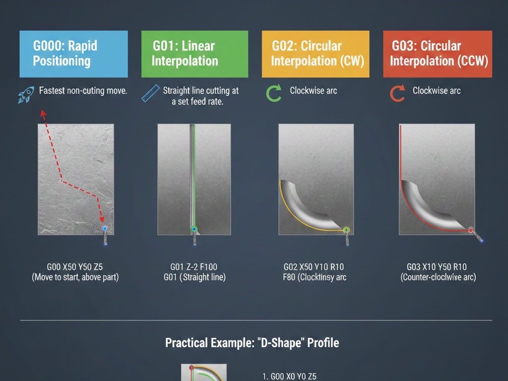
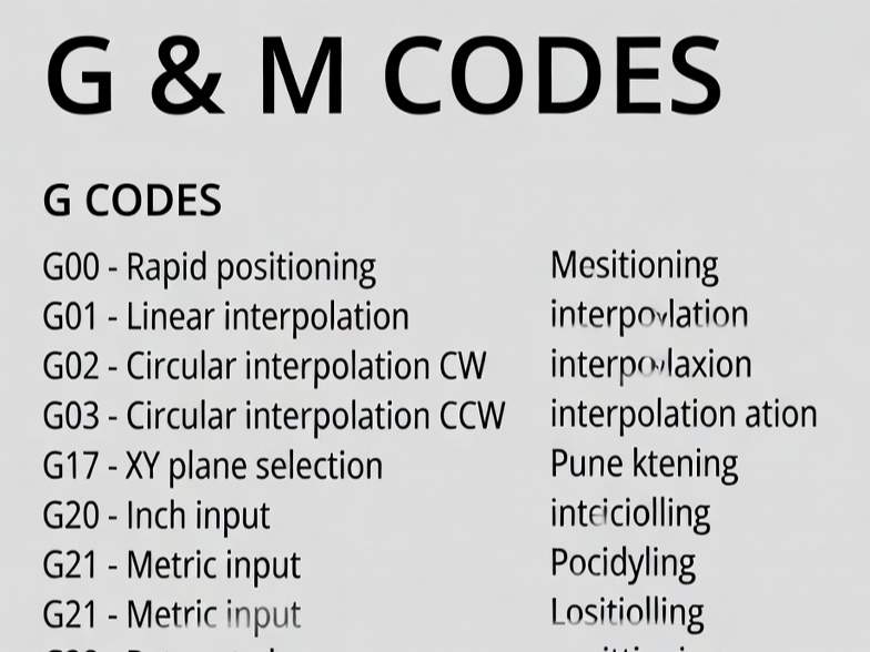
| G00 | Rapid positioning (fast move, no cutting) | G00 X100 Y50 Z5 | Moves quickly to X100, Y50, Z5 without cutting. |
| G01 | Linear interpolation (straight cut at feed rate) | G01 X200 Y100 F150 | Cuts straight line to X200, Y100 at 150 units/min feed. |
| G02 | Circular interpolation clockwise (arc) | G02 X50 Y50 I10 J0 F100 | Clockwise arc to X50 Y50, center offset I10 (X), J0 (Y). |
| G03 | Circular interpolation counterclockwise | G03 X50 Y50 I-10 J0 F100 | Counterclockwise arc with center offset. |
| G04 | Dwell (pause) | G04 P2.0 or G04 X2.0 | Pauses for 2 seconds (clears chips or allows settling). |
Other essential G-codes:
- Coordinate and Units:
- G20: Inch units
- G21: Millimeter units (common default)
- G90: Absolute positioning (coordinates from origin)
- G91: Incremental positioning (relative to current position)
- Plane Selection (for arcs):
- G17: XY plane (default for milling)
- G18: XZ plane
- G19: YZ plane
- Compensation:
- G40: Cancel cutter radius compensation
- G41: Cutter compensation left
- G42: Cutter compensation right (offsets tool path for diameter)
- Work Offsets:
- G54-G59: Select work coordinate systems (fixtures/origins)
- Canned Cycles (repetitive drilling/milling, simplify code):
- G81: Simple drilling cycle
- G82: Drilling with dwell
- G83: Peck drilling (chip breaking)
- G84: Tapping
Example canned cycle (drilling holes):
G81 R5.0 Z-20.0 F100 (Retract to Z5, drill to Z-20 at feed 100)
X10 Y10 (Drill first hole)
X30 Y30 (Second hole)
G80 (Cancel cycle)
These cycles reduce repetitive code for hole patterns.
Common M-Codes: Machine Functions
M-codes control non-geometric actions. Fewer are standardized; many are machine-specific.
| M-Code | Description | Example |
|---|---|---|
| M00 | Program stop (operator intervention) | M00 (Pauses; press cycle start to resume) |
| M01 | Optional stop (if enabled) | Similar to M00 but ignorable |
| M03 | Spindle on clockwise | M03 S2000 (Start spindle at 2000 RPM) |
| M04 | Spindle on counterclockwise | For reverse tapping |
| M05 | Spindle stop | M05 |
| M06 | Tool change | T05 M06 (Select tool 5, change) |
| M08 | Coolant on (flood) | M08 |
| M09 | Coolant off | M09 |
| M30 | Program end and rewind | Ends program, resets to start |
Other common: M98 (call subprogram), M99 (return from subprogram).
Full Program Examples
Simple Milling Example: Square Pocket
This program mills a 50x50mm square pocket, 10mm deep.
% (Program start)
O1000 (Program number)
G21 G17 G90 (Metric, XY plane, absolute)
G54 (Work offset)
T01 M06 (Tool change to 10mm endmill)
G43 H01 Z50 (Tool length compensation)
S5000 M03 (Spindle 5000 RPM clockwise)
G00 X0 Y0 Z5 (Rapid to start)
M08 (Coolant on)
G01 Z-10 F200 (Plunge to depth)
G01 X50 F300 (Cut side 1)
G01 Y50 (Side 2)
G01 X0 (Side 3)
G01 Y0 (Side 4)
G00 Z50 (Retract)
M09 (Coolant off)
M05 (Spindle stop)
G00 X0 Y0 Z100 (Home)
M30 (End program)
%
Explanation: Starts with safe setup, rapid positions, linear cuts, retracts, ends cleanly.
Drilling Example with Canned Cycle
Drill 4 holes in a square pattern.
G21 G90 G17
G54
T02 M06 (Drill tool)
G43 H02
S3000 M03
G00 X10 Y10 Z10
G81 R3 Z-15 F150 (Drill cycle: retract 3, depth -15)
X10 Y40
X40 Y40
X40 Y10
G80 (Cancel)
G00 Z50
M05 M09
M30
Lathe Turning Example
Simple facing and turning.
O2000
G21 G97 G99 (Metric, constant RPM, feed/rev)
T0101 M06 (Tool 1)
G50 S2000 (Max spindle 2000)
G96 S200 M03 (Constant surface speed 200 m/min, CW)
G00 X50 Z2 (Rapid to start)
G01 Z-30 F0.2 (Face)
G00 X0 Z2
G01 X45 Z-50 (Turn diameter)
G00 X100 Z100 (Retract)
M05
M30
Best Practices and Advanced Notes
- Safe Start Block: Always begin with
G00 G17 G21 G40 G49 G80 G90to reset modes and avoid crashes. - Comments: Use parentheses
(Comment here)for clarity. - Feed (F) and Speed (S): Set appropriately; F for feed rate, S for spindle.
- Subprograms: Use M98/M99 for repetitive features.
- Variations: Haas might use different M-codes for coolant; check manuals.
- Modern Use: CAM generates code, but hand-editing fixes issues or adds macros.
G and M codes enable precise, repeatable manufacturing in industries like aerospace and automotive. Mastering them improves efficiency and reduces errors.