Short CNC Pocket Milling Program Example and Explanation
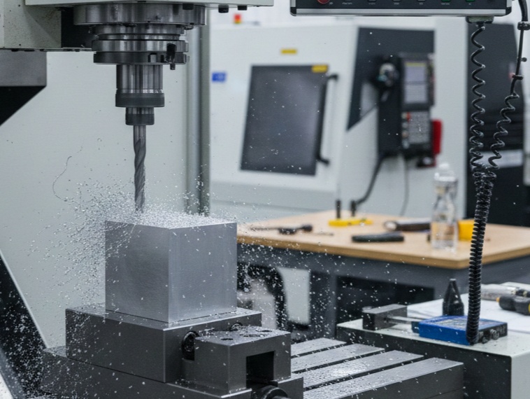
CNC Pocket Milling is a very important process. It is a process in which a specific depth of a box, cavity or hole (Pocket) is cut out by a CNC machine inside a metal block (Workpiece).
In simple words, its purpose is to empty the interior of a material to a specific shape and depth, instead of cutting it completely from the top, so that another object bearing or any other part can fit in it.
In this guide, we will create a short CNC pocket milling program and explain each line in simple terms.
What Is Pocket Milling?
Pocket milling is a machining process in which a cutting tool removes material from an enclosed area of a workpiece.
For example, suppose we need to machine a 40 mm × 30 mm rectangular pocket that is 5 mm deep.
The basic operation is:
- Position the tool above the workpiece.
- Move to the pocket starting position.
- Lower the cutter to the required depth.
- Move around the pocket area.
- Remove the material using one or more passes.
- Retract the tool safely.
A simple pocket program can be written using standard G-code commands such as:
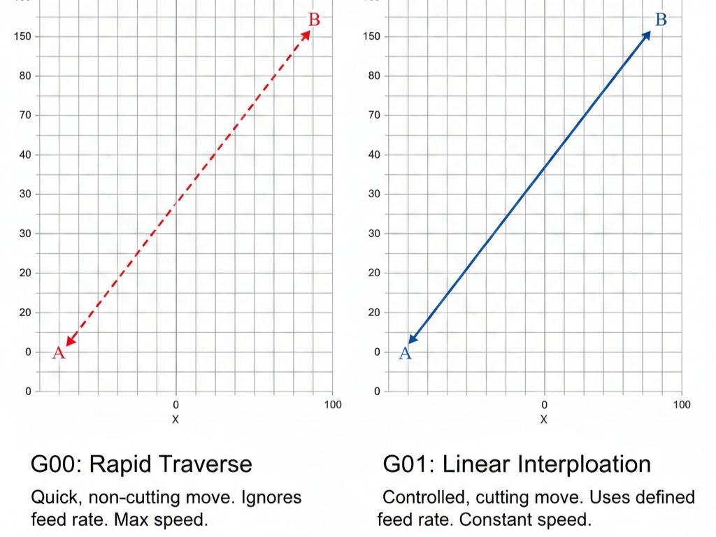
- G00 – Rapid positioning
- G01 – Linear interpolation
- G17 – XY plane selection
- G21 – Metric programming
- G90 – Absolute programming
- G54 – Work coordinate system
- M03 – Spindle ON clockwise
- M05 – Spindle stop
- M30 – Program end and reset
Short CNC Pocket Milling Program Example
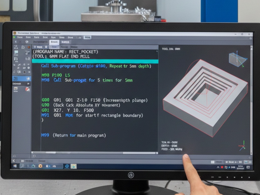
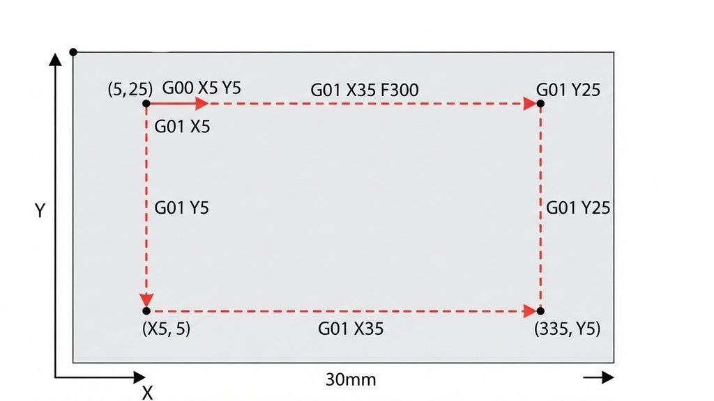
The following example shows a simple rectangular pocket milling operation.
Pocket size: 40 mm × 30 mm
Depth: 5 mm
Tool: 10 mm end mill
O1001
G21 G17 G90 G40 G49 G80
G54
T1 M06
S2500 M03
G00 X5 Y5
G43 H01 Z50
M08
G00 Z5 G01 Z-2.5 F100
G01 X35 F300
G01 Y25
G01 X5
G01 Y5
G01 X35
G01 Y25
G00 Z50
M09
M05
G91 G28 Z0
G90
M30
Code Explanation
O1001 is the program number.
G21 G17 G90 G40 G49 G80
G21 – The program uses millimeters.
G17 – Selects the XY plane.
G90 – Absolute positions from the work coordinate origin.
G40 – Cutter Compensation Cancel.
G49 – Tool Length Compensation Cancel.
G80 – Cancels any previously active canned drilling or machining cycle.
G54 selects the first common work coordinate system.
T1 M06 select the Cutting Tool.
S2500 M03
S2500 the spindle speed is: 2500 RPM.
M03 starts the spindle in the clockwise direction.
G00 commands rapid positioning.
G43 H01 Z50
G43 activates positive tool length compensation.
H01 selects the tool length offset associated with Tool 1.
Z50 the machine to move to Z50 while applying the tool length offset.
M08 coolant on.
G00 Z5 the tool moves rapidly to: Z = 5 mm.
G01 Z-2.5 F100
G01 linear interpolation. The cutter moves down to:
Z = -2.5 mm This creates the first cutting pass.
The feed rate is:
F100 feed rate: 100 mm/min in this example.
G01 X35 F300
G01 Y25
G01 X5
G01 Y5
The cutter moves:
From X5 to X35
From Y5 to Y25
From X35 back to X5
From Y25 back to Y5
G01 X35
G01 Y25
Another movement through the pocket area.
G00 Z50 the cutter rapidly retracts to Z50.
M09 turns coolant off.
M05 stops the spindle.
G91 G28 Z0
G91 selects incremental programming.
G28 Z0 commands the Z axis to return toward the machine reference position.
M30 ends the program.
Related: Rectangular Pocket Milling