Fanuc CNC Alarm Codes: Comprehensive Guide for Operators
Fanuc CNC machines are widely used in manufacturing for their precision, reliability, and advanced automation. Like any sophisticated machinery, they are equipped with a comprehensive alarm system that alerts operators to errors, malfunctions, or conditions requiring attention.
Understanding Fanuc Alarm Codes is essential for CNC operators, programmers, and maintenance technicians. Each code corresponds to a specific issue, providing information about the cause and recommended solution, which helps minimize downtime, prevent damage, and maintain optimal machine performance.
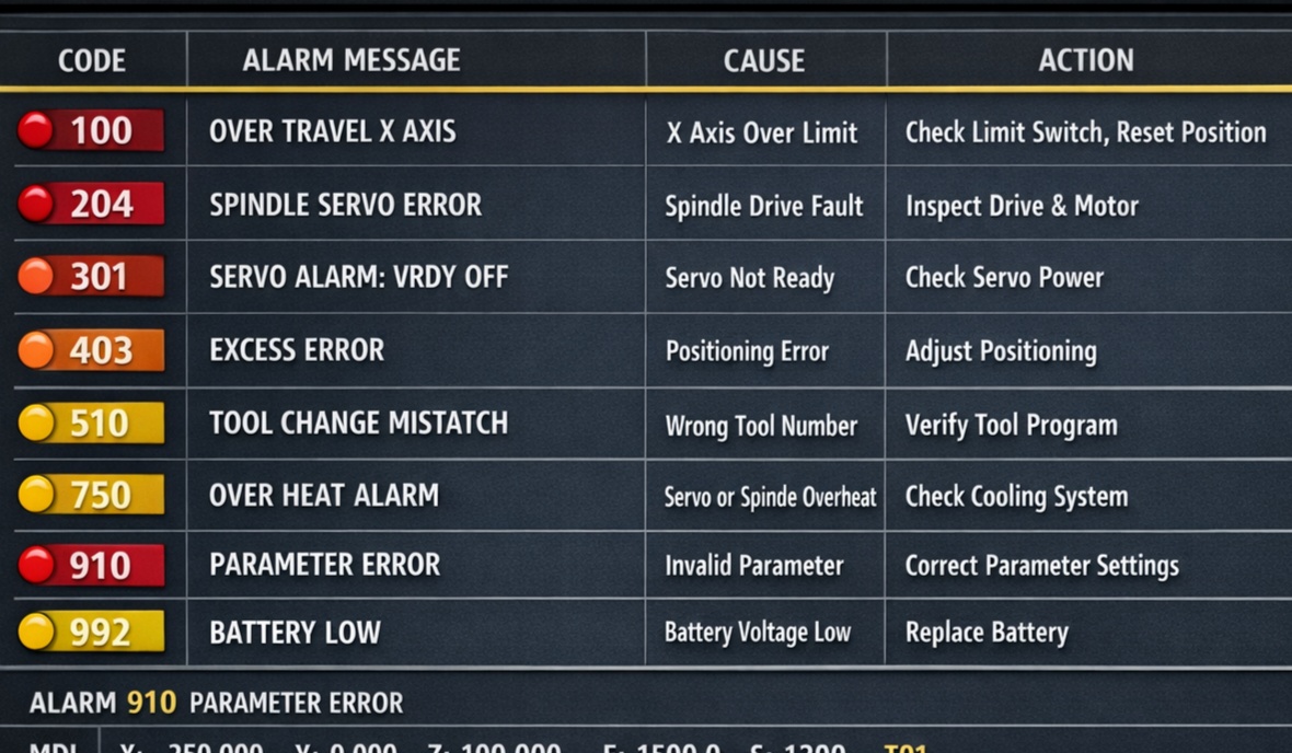
Complete list of common Fanuc alarm codes, organized with their messages, causes, and suggested actions.
1. Program & Command Alarms (PS Alarms)
These are typically “soft” alarms related to G-code errors or programming logic.
| Code | Alarm Name | Description & Solution |
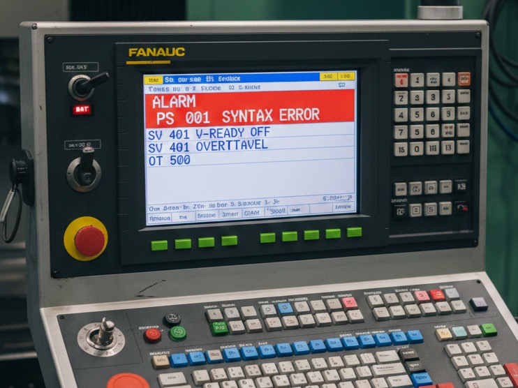
| 001 | BP/S Alarm | An address was specified without a following value. Check your G-code syntax. |
| 004 | Address Not Found | A block contains an unknown address or illegal character. |
| 010 | Improper G-Code | An unusable G-code or a code for a function not provided is specified. |
| 030 | Illegal Offset Value | The tool offset value is too large or outside the allowed range. |
| 114 | Format Error in Macro | A syntax error occurred in a Custom Macro statement. |
2. Background Edit Alarms (BP/S)
These occur when you are editing a program while another is running.
- BP/S 085: Communication error. Usually occurs when transferring programs via RS-232 and the baud rate or stop bits don’t match.
- BP/S 086: DR Signal off. The I/O device is not powered on or the cable is disconnected.
3. Servo Alarms (SV Alarms)
These indicate issues with the motors, encoders, or power amplifiers. These often require a machine restart.
- SV 401: V-Ready Off. The servo amplifier “ready” signal is not turned on. Often caused by an emergency stop or a faulty power supply.
- SV 414: Digital Servo Alarm. A detection error occurred in a specific axis. Check the diagnostic screen (No. 200 or 204) to see if it’s an Overload (OVL) or Overcurrent (OVC).
- SV 438: Abnormal Current. High current was detected in the motor circuit. Could be a short circuit in the motor cable or a seized mechanical component.
4. Overtravel Alarms (OT Alarms)
These trigger when the machine moves past its physical or software-defined safety limits.
- OT 500: Positive Overtravel. The axis reached the software limit in the positive direction.
- OT 501: Negative Overtravel. The axis reached the software limit in the negative direction.
- OT 506: Hardware Overtravel. The axis hit the physical limit switch. You must hold the “Overtravel Release” button while jogging the axis in the opposite direction.
5. Spindle Alarms (SP Alarms)
Specific to the spindle motor and drive unit.
- SP 749: Spindle Serial Link Error. Communication between the CNC and the spindle amplifier is broken.
- SP 9001: Motor Overheat. The spindle is working too hard or the cooling fan has failed.
- SP 9012: Overcurrent. The power circuit in the spindle drive detected a surge.
6. System Alarms (SYS Alarms)
These are critical hardware failures involving the CNC control board or memory.
- SYS 910: RAM Parity Error. A problem with the internal memory. This often requires a memory clear and reloading of parameters.
- SYS 930: CPU Error. The main processor has encountered a fatal interrupt.
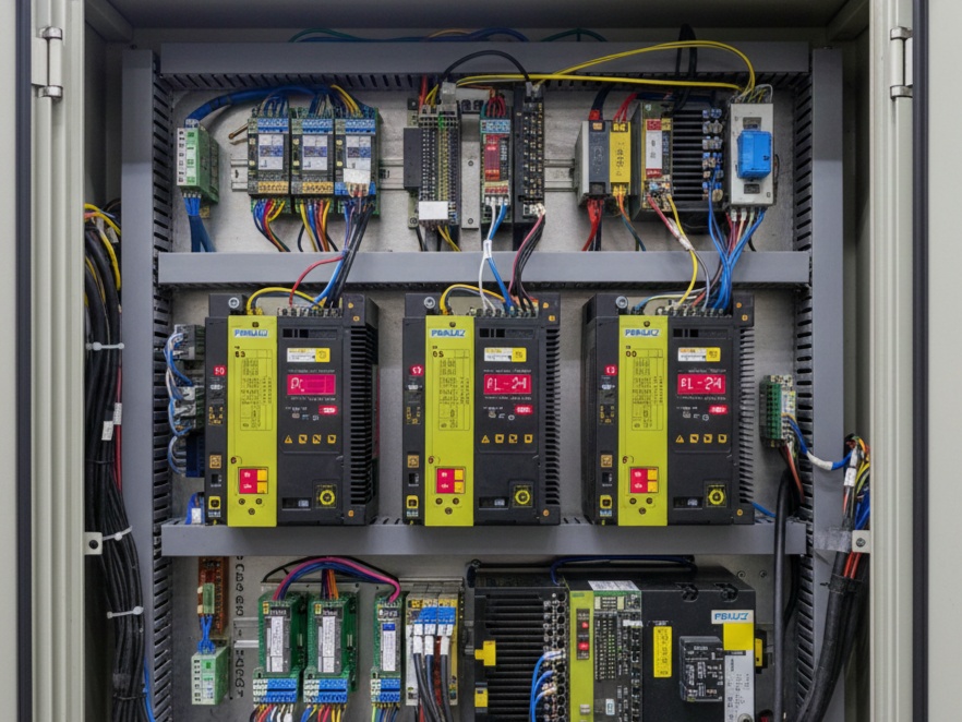
7. Spindle & Servo Drive Error Codes (LED Displays)
When a 400 or 700-series alarm appears on the screen, you should look at the physical drive units inside the electrical cabinet. The small 7-segment LED display on the drive will show a number or letter.
| LED Code | Meaning | Common Fix |
| 01 | Overcurrent | Check for a short in the motor power cable. |
| 02 | Control Voltage Low | The 24V power supply to the drive is dropping. |
| 12 | Overcurrent (Spindle) | Possible short in the spindle windings or failed IGBT module. |
| AL-24 | Serial Link Error | Check the optical fiber or JD1B/JD1A cables between drives. |
8. Memory & Battery Alarms
These alarms are “warnings” that something is about to go wrong with your data.
- APC 300: Request for Reference Position Return. The machine lost its “home” position because the absolute pulse coder battery died.
- APC 306-308: Battery Voltage Low. The 6V battery pack in the servo drive needs to be replaced. Do not turn off the machine power while replacing these, or you will lose your home position.
- BAT: (Flashing at bottom of screen). The 3V lithium battery on the main CNC CPU board is low. Replace this immediately to avoid losing all parameters and programs.
9. Communication & I/O Alarms
These occur during “Handshaking” between the CNC and a PC or Robot.
- PS 085: RS-232C communication error. Check that your Baud Rate (Para 552), Stop Bits (Para 101), and Data Bits match your PC software.
- PS 087: Buffer Overflow. The PC is sending data faster than the Fanuc can read it. You need to enable XON/XOFF software handshaking.
10. External / PMC Alarms (1000+ Range)
Alarms numbered 1000 and higher are not written by Fanuc; they are written by the Machine Tool Builder (MTB) like Haas, Mori Seiki, or Doosan.
- 1000 – 1999: Usually related to the “Ladder” logic.
- Common Examples: * “Lube Level Low”
- “Coolant Motor Overload”
- “Chuck Unclamped”
- “Door Interlock Open”
Tip: For 1000+ alarms, you must check the machine’s specific maintenance manual, not the Fanuc manual, because these alarms are custom-defined for that specific machine model.
Critical Troubleshooting Steps
If you are stuck on a specific alarm, follow this sequence:
- Check Diagnostic 200-204: These bits tell you why a servo alarm is happening (e.g., if bit #7 is “1”, it’s an overheat).
- Check Diagnostic 700-701: These bits provide the same level of detail for spindle alarms.
- Check the Power Supply: If multiple drives show alarms simultaneously, the Power Supply Module (PSM) is usually the culprit.
To dive deeper, the most powerful way to troubleshoot a Fanuc system is by looking at the Diagnostic Bits. When a general alarm like 414 (Servo) or 749 (Spindle) appears, the CNC is actually hiding the specific cause in the Diagnostic screen.
Here is the “secret” key to reading those bits (No. 200, 204, 700, and 701):
1. Servo Alarm Bits (Diagnostic No. 200 & 204)
When you see Alarm 414, go to [SYSTEM] -> [DIAGN] -> 200. You will see 8 bits (0 or 1).
Diagnostic No. 200 (Main Servo Faults)
| Bit | Name | Meaning if “1” | Common Cause |
| #7 | OVL | Overload | Mechanical bind, bad bearings, or heavy cutting. |
| #6 | LV | Low Voltage | Power supply issue or a drop in the 24V line. |
| #5 | OVC | Overcurrent | Potential short in motor power cable or motor winding. |
| #4 | HCA | Abnormal Current | Likely a hardware failure in the Servo Amplifier. |
| #3 | HVA | Overvoltage | DC Link voltage too high (often during rapid deceleration). |
| #2 | DCA | Discharge Alarm | Regenerative discharge circuit failure. |
| #1 | FBA | Disconnection | Feedback cable is loose or broken (Pulse Coder error). |
Diagnostic No. 204 (Advanced Servo Faults)
- Bit #6 (OFS): A/D converter error inside the digital servo (Drive needs replacement).
- Bit #5 (MCC): Magnetic Contactor contacts are welded or failed to close.
2. Spindle Alarm Bits (Diagnostic No. 700 & 701)
If you have a 700-series alarm, these bits tell you why the spindle isn’t turning or why it tripped.
Diagnostic No. 700
- Bit #4 (SVE): Spindle Servo connection error.
- Bit #7 (OT): Over-travel (Spindle specific).
Diagnostic No. 701
- Bit #7 (ALM): A specific alarm is detected in the Spindle Amplifier (Check the LED on the drive!).
3. The “Battery” Troubleshooting
If you see APC or 300 alarms, your machine has lost its “Home” (Reference) position.
- Don’t Turn the Power Off: If the screen says “Battery Low,” keep the machine ON while you swap the batteries. If you turn it off, you lose the parameters.
- The “P + CAN” Trick: If you have a soft overtravel alarm (500/501) that won’t clear after you’ve moved the axis back, hold [P] and [CAN] keys while powering up the CNC. This bypasses the software limits during the boot-up so you can zero-return the machine.
4. Quick Hardware Cross-Check
If you aren’t sure if the Drive or the Motor is bad:
- Swap the Cables: If you have two identical axes (like X and Y), swap the command cables at the drives.
- Check the Alarm: If the alarm stays on the same drive, the Drive is bad. If the alarm moves to the other axis, the Motor or Cable is bad.
Download the complete Fanuc Alarm Codes PDF which includes over 100 common CNC alarm codes with clear descriptions, possible causes, and recommended solutions. This guide is helpful for CNC operators, programmers, and maintenance engineers to quickly troubleshoot Fanuc CNC machines and reduce downtime.