Most Common CNC Programming Mistakes & How to Fix Them
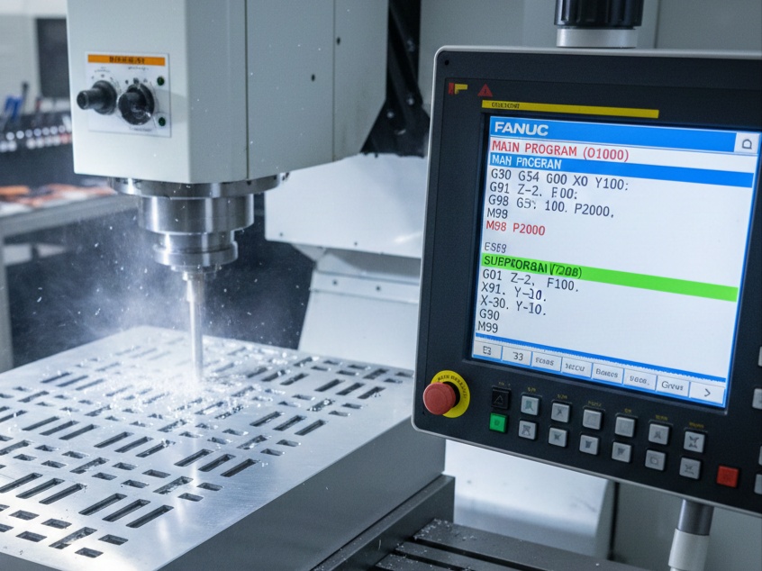
CNC programming is the bridge between a digital design and a physical part. Even a single character error in a G-code line can lead to scrapped parts, broken tools, or a costly machine crash.
Below are the most common CNC programming mistakes and the practical steps to fix them.
1. Syntax and Formatting Errors
This is the “typo” of the CNC world. Machines are extremely literal; they cannot “guess” what you meant.
- The Mistake: Confusing the letter “O” (program number) with the number “0” (zero), or omitting a decimal point (e.g., writing
X10instead ofX10.0). In many controllers,X10might be interpreted as 10 microns (0.01 mm) instead of 10 mm. - The Fix: Use G-code editors with syntax highlighting. Always use a decimal point for coordinates, even for whole numbers.
2. Missing or Inadequate Safety Blocks
Every program should begin with a “safety block” to ensure the machine is in a known state.
- The Mistake: Assuming the machine is in the correct mode (e.g., Absolute vs. Incremental). If the previous job used
G91(Incremental) and your new program starts withoutG90(Absolute), the tool will move to the wrong location. - The Fix: Start every program with a standard safety line:
G00 G17 G20 G40 G80 G90(Cancel compensation, cancel canned cycles, set to absolute mode and XY plane).
3. Incorrect Tool Offsets and Lengths
The machine needs to know exactly how long each tool is and where it sits in the holder.
- The Mistake: Forgetting to activate tool length compensation with
G43or using the wrongHorDoffset value. This often results in the tool “cutting air” or plunging straight into the workpiece. - The Fix: Double-check that your
T(Tool number) matches yourH(Length offset) andD(Diameter offset).- Example:
T01 M06followed byG43 H01 Z1.0.
- Example:
4. Improper Feeds and Speeds
Programming the wrong spindle speed (S) or feed rate (F) can ruin a part in seconds.
- The Mistake: Using the same settings for different materials (e.g., running aluminum settings on stainless steel) or setting a feed rate that is too high for the tool’s chip load capacity.
- The Fix: Use a speed and feed calculator or refer to the tool manufacturer’s data. If you aren’t sure, start at 50%–70% of the recommended speed and “dial it in” using the machine’s manual override knobs.
5. Toolpath Collisions and Entry/Exit Errors
How a tool enters and leaves the material is just as important as the cut itself.
- The Mistake: Rapidly moving (
G00) into a workpiece or failing to clear a clamp during a transition move. - The Fix: Always simulate your toolpaths in CAM software before sending them to the machine. Use a “Dry Run” (running the program with no material and the Z-axis offset high) to visually verify clearance.
Summary Checklist for Error-Free Programming
| Feature | What to Check |
| Units | Ensure G20 (Inches) or G21 (Metric) matches your drawing. |
| Planes | Ensure G17/18/19 is correctly set for circular interpolation. |
| Offsets | Verify G54–G59 work coordinates are set at the machine. |
| Comments | Add labels (e.g., (ROUGH ENDMILL)) to make the code readable. |