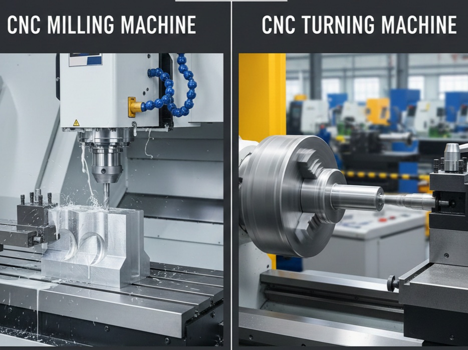
Fanuc CNC Lathe Programming Basics
CNC (Computer Numerical Control) lathe programming might seem like learning a foreign language at first, but it follows a very logical structure. Most industrial lathes use Fanuc-style controls, which rely on G-codes (preparatory functions) and M-codes (miscellaneous functions) to tell the machine exactly how to move, spin, and cut.
Think of a CNC program as a recipe: you define the tools, set the speeds, and then provide a list of coordinates for the “knife” to follow.
1. The Coordinate System: X and Z
Before writing code, you must understand how the machine sees space. In a standard 2-axis CNC lathe:
- Z-axis: Runs parallel to the spindle (the length of the part). Moving toward the chuck is Z-negative (-); moving away is Z-positive (+).
- X-axis: Controls the diameter of the part. Moving toward the center line is X-minus; moving away is X-plus.
Pro Tip: In CNC lathe programming, X-values are almost always programmed as the diameter of the part, not the radius. If you want a 50mm pin, you program
X50.0.
2. Program Structure
Every Fanuc program follows a specific “sandwich” structure:
The Header
- O1234: The program number (always starts with ‘O’).
- G21 (or G20): G21 for Metric (mm), G20 for Inch.
- G28 U0 W0: Sends the machine to its “Home” position to ensure a safe start.
The Tool Call
- T0101: This tells the machine to rotate to Tool 01 and activate Offset 01.
The Spindle Start
- G96 S200 M03: G96 is Constant Surface Speed (CSS). The machine adjusts the RPM automatically as the diameter changes to keep cutting conditions optimal. S200 is the speed, and M03 starts the spindle clockwise.
- G50 S2500: Limits the maximum RPM so the machine doesn’t spin dangerously fast at the center.
3. Essential G-Codes for Beginners
These are the “bread and butter” codes you will use 90% of the time.
| Code | Function | Description |
| G00 | Rapid Traverse | Moves the tool at max speed (used for positioning, not cutting). |
| G01 | Linear Interpolation | Moves the tool in a straight line at a specific feed rate (cutting). |
| G02 / G03 | Circular Interpolation | G02 is clockwise arcs; G03 is counter-clockwise arcs. |
| G71 | Roughing Cycle | A “canned cycle” that removes bulk material automatically. |
| G70 | Finishing Cycle | Used after G71 to take a final, clean pass. |
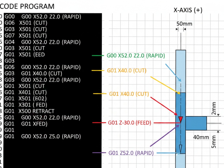
4. Writing a Simple Program
Let’s look at a basic script to turn a 50mm diameter bar down to 40mm over a length of 30mm.
G-Code
O0001 (SAMPLE PART)
G21 G40 G99 (Metric, Cancel Comp, Feed per Rev)
G28 U0 W0 (Home)
T0101 (Select Tool 1)
G96 S180 M03 (Start Spindle CSS)
G50 S2000 (Max RPM)

(Approaching Part)
G00 X52.0 Z2.0 M08 (Rapid to start point, Coolant on)

(Cutting Pass)
G01 X40.0 F0.2 (Move to 40mm diameter)
G01 Z-30.0 (Cut 30mm deep)
G01 X52.0 (Retract diameter)

(Ending)
G00 Z5.0 M09 (Move away, Coolant off)
G28 U0 W0 (Home)
M30 (Program End & Reset)
5. The Power of Canned Cycles (G71)
Writing every single line for multiple passes is tedious. Fanuc uses G71 to simplify this. You define the final shape, and the controller calculates all the intermediate “roughing” passes for you.
G71 Structure:
- Line 1: Defines the depth of cut and the retract amount.
- Line 2: Defines the start/end block numbers of the profile and the finishing allowance (material left for the final pass).
6. Safety and Best Practices
- Decimal Points are Mandatory: In Fanuc,
X50might be read as 0.050mm. Always writeX50.0. - The “Single Block” Rule: When running a program for the first time, use “Single Block” mode to execute one line at a time and keep your hand near the E-Stop.
- Check Your Offsets: Most crashes happen because the machine doesn’t know exactly where the tool tip is. Always double-check your Tool Geometry offsets.
Summary Checklist for Beginners
- [ ] Did I include a spindle speed limit (G50)?
- [ ] Are my X coordinates in Diameter?
- [ ] Did I use G00 for air moves and G01 for cutting?
- [ ] Is there an M30 at the very end?